Dedicated circuit wiring diagram ground fault interrupter gfci outlet png image transpa free on seekpng how to wire a half switched install flex socketsandswitches com connections tutorial eight receptacle s electrical online for 20a gfi with switch doityourself community forums wall diagrams do it yourself help procedure and an explained etechnog connection house i want the following from source hot 3 way dengarden installing duplex receptacles ceiling fan add new light fixture outlets switches split recepticle 101 4 two in one box dryer sy sa 120v branch circuits high resolution explorist life cj tech 53482 dual usb instruction manual manuals plug boat connect ac boats combo 220 volt askmediy multiple radial ring mains electronics engineering or archives page 2 of size required choose proper

Dedicated Circuit Wiring Diagram Ground Fault Interrupter Gfci Outlet Png Image Transpa Free On Seekpng

How To Wire A Half Switched Outlet

How To Install A Flex Outlet Socketsandswitches Com

Connections Tutorial Eight Receptacle S

Wiring A Switched Outlet Diagram Electrical Online

Wiring Diagram For 20a Gfi Outlet With Switch Doityourself Com Community Forums
Switched Wall Outlet Wiring Diagrams Do It Yourself Help Com
Procedure And Diagram For Wiring An Outlet Explained Etechnog
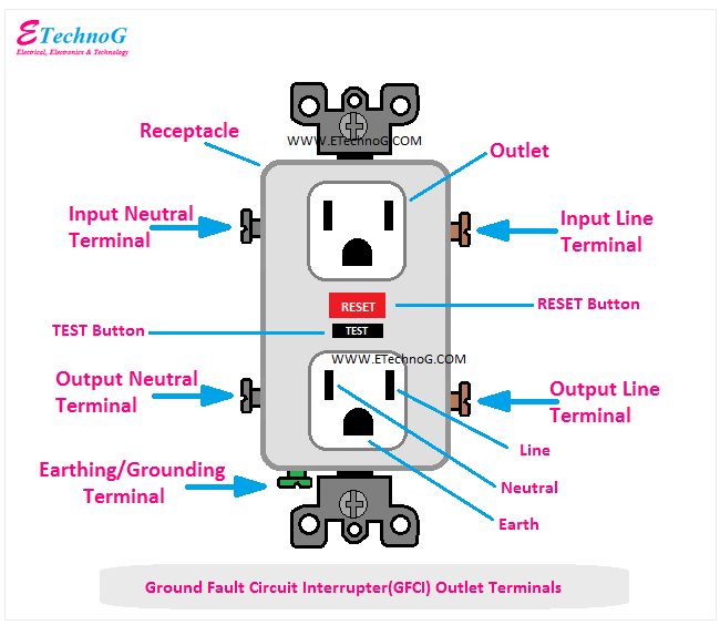
Gfci Outlet Wiring And Connection Diagram Etechnog

House Electrical Wiring Connection Diagrams
I Want To Wire The Following Diagram From Source Switched Receptacle Switch Hot Outlet

How To Wire A 3 Way Switch Wiring Diagram Dengarden

Installing Switched Duplex Receptacles
Switched Wall Outlet Wiring Diagrams Do It Yourself Help Com

Ceiling Fan Wiring Diagrams
Procedure And Diagram For Wiring An Outlet Explained Etechnog
Add A New Light Fixture Wiring Diagrams Do It Yourself Help Com
/tips-for-wiring-outlets-and-switches-1824668-schema-cd5df872c6884b54b85042231387b4ea.jpeg?strip=all)
How To Wire Electrical Outlets And Switches

Split Recepticle Wiring Electrical 101
Dedicated circuit wiring diagram ground fault interrupter gfci outlet png image transpa free on seekpng how to wire a half switched install flex socketsandswitches com connections tutorial eight receptacle s electrical online for 20a gfi with switch doityourself community forums wall diagrams do it yourself help procedure and an explained etechnog connection house i want the following from source hot 3 way dengarden installing duplex receptacles ceiling fan add new light fixture outlets switches split recepticle 101 4 two in one box dryer sy sa 120v branch circuits high resolution explorist life cj tech 53482 dual usb instruction manual manuals plug boat connect ac boats combo 220 volt askmediy multiple radial ring mains electronics engineering or archives page 2 of size required choose proper


