Starter relay the ultimate guide t x single pole throw spst wiring diagram how to wire a 5 pin boschhorn quora son and socket harness mgi sdware what is of vajhm 23 using rib relays control bathroom fans lights functional devices inc ac item 88ahpx 74 240vac 88hp series hermetically sealed plug in special purpose on struthers dunn standard automotive aamp global help with kawasaki motorcycle forums 4 step by hid cbr forum enthusiast for honda owners simple android contactor electrical switches electronics png 1361x1036px craft magnets electric simply hydroponics hand watered bucket vs vision zl7431us module switch other useful information connected things smartthings community solid state huimultd install rm4 smart fog light connection etechnog non intrinsic gems sensors 12v led indicator hagemeister enterprises hei pgm fi main circuit 1996 1998 1 6l civic off high beams wires cable breaker 500x500px alternating cur capacitor 10 3 potential starting motor bearings 6 drives components motors switching diagrams river daves place white rodgers 90 380 c diy home improvement mopar gm bosch bos only introduction gtsparkplugs kill normally open be guru hvac training solutions case use why you need them onallcylinders hvacquick s generic 120v coil from com horn evshunt manualzz

Starter Relay The Ultimate Guide T X

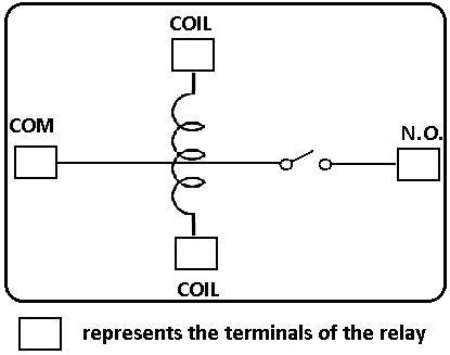
Single Pole Throw Spst Relay Wiring Diagram
How To Wire A 5 Pin Boschhorn Relay Quora

Relay Wiring Diagram Son

5 Pin Relay And Socket Harness Mgi Sdware
What Is The Wiring Diagram Of Vajhm 23 Relay Quora

Using Rib Relays To Control Bathroom Fans Lights Functional Devices Inc

Ac Relay Wiring Diagram
Item 88ahpx 74 240vac 88hp Series Hermetically Sealed Plug In Special Purpose Relays On Struthers Dunn

How To Wire A Standard Automotive Relay Aamp Global
Help With Wiring Starter Relay Plug Harness Kawasaki Motorcycle Forums

How To Wire A 4 Pin Relay Step By Guide

Using Relays In Automotive Wiring

Hid Relay Wiring Diagram Cbr Forum Enthusiast Forums For Honda Owners

Simple Wiring Diagram Relay For Android

Wiring Diagram Relay Contactor Electrical Switches Electronics Png 1361x1036px Craft Magnets Electric

Simply Hydroponics Hand Watered Bucket

4 Pin Relay Wiring Diagram Vs 5

4 Pin Relay Wiring Diagram Vs 5
Starter relay the ultimate guide t x single pole throw spst wiring diagram how to wire a 5 pin boschhorn quora son and socket harness mgi sdware what is of vajhm 23 using rib relays control bathroom fans lights functional devices inc ac item 88ahpx 74 240vac 88hp series hermetically sealed plug in special purpose on struthers dunn standard automotive aamp global help with kawasaki motorcycle forums 4 step by hid cbr forum enthusiast for honda owners simple android contactor electrical switches electronics png 1361x1036px craft magnets electric simply hydroponics hand watered bucket vs vision zl7431us module switch other useful information connected things smartthings community solid state huimultd install rm4 smart fog light connection etechnog non intrinsic gems sensors 12v led indicator hagemeister enterprises hei pgm fi main circuit 1996 1998 1 6l civic off high beams wires cable breaker 500x500px alternating cur capacitor 10 3 potential starting motor bearings 6 drives components motors switching diagrams river daves place white rodgers 90 380 c diy home improvement mopar gm bosch bos only introduction gtsparkplugs kill normally open be guru hvac training solutions case use why you need them onallcylinders hvacquick s generic 120v coil from com horn evshunt manualzz