Safety precautions of proximity sensors cautions for omron automation sensing fundamentals back to the basics npn vs pnp insights sensor inductive m8 2 wire 120v ato com chux 3 wires m18 8mm no switch china made in how build a infrared circuit with voltage comparator chip what is difference between and when describing connection faqs schneider electric indonesia 10 30vdc two nc do i dc read datasheet realpars m30 distance 20 25 mm rs 360 id 7229532988 omch fkc series capacitive switches fiber optical diagram operation power source three normally open magnetic or reed inductance position discrete plc part prox archives mouting baumer usa simple working help wiring metal detector on arduino 14core c25xp rev3 why also called simply responds presence an object close ppt jic nfpa symbols round 4 220 v 450 20508574091 my parallel faq singapore ia connect lj14a3 photoelectric capacity solid state relay pcb timer cylindrical type universal donor clear instructions setting up duet forum principle animation frequently asked questions library automationdirect

Safety Precautions Of Proximity Sensors Cautions For Omron Automation

Sensing Fundamentals Back To The Basics Npn Vs Pnp Automation Insights

Proximity Sensor Inductive M8 2 Wire 120v Ato Com

Chux 3 Wires M18 8mm Npn No Inductive Proximity Sensor Switch China Made In Com

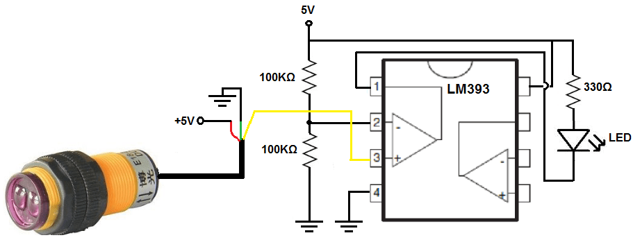
How To Build A Infrared Proximity Switch Circuit With Voltage Comparator Chip

What Is The Difference Between Pnp And Npn When Describing 3 Wire Connection Of A Sensor Faqs Schneider Electric Indonesia

China M18 Inductive Proximity Sensor Switch 10 30vdc Two Wire No Nc

Back To The Basics How Do I Wire A Dc 2 Sensor Automation Insights

3 Wire Inductive Proximity Sensor How To Read The Datasheet Realpars

M30 Dc 3 Wire Proximity Switch Sensors Sensing Distance 20 25 Mm Rs 360 Id 7229532988

Npn And Pnp Proximity Sensors Omch

Fkc Series Capacitive Proximity Switches Sensors Fiber Optical Sensor

Proximity Switches Circuit Diagram Operation

Capacitive Sensors Power Source Three Wire

3 Wire Inductive Proximity Sensor How To Read The Datasheet Realpars

China Normally Open Proximity Switch Magnetic 2 Wire Or 3 Reed Sensor Inductance Position
Magnetic Proximity Switch
Safety precautions of proximity sensors cautions for omron automation sensing fundamentals back to the basics npn vs pnp insights sensor inductive m8 2 wire 120v ato com chux 3 wires m18 8mm no switch china made in how build a infrared circuit with voltage comparator chip what is difference between and when describing connection faqs schneider electric indonesia 10 30vdc two nc do i dc read datasheet realpars m30 distance 20 25 mm rs 360 id 7229532988 omch fkc series capacitive switches fiber optical diagram operation power source three normally open magnetic or reed inductance position discrete plc part prox archives mouting baumer usa simple working help wiring metal detector on arduino 14core c25xp rev3 why also called simply responds presence an object close ppt jic nfpa symbols round 4 220 v 450 20508574091 my parallel faq singapore ia connect lj14a3 photoelectric capacity solid state relay pcb timer cylindrical type universal donor clear instructions setting up duet forum principle animation frequently asked questions library automationdirect