How to wire a jon boat wiring guide flat bottom world mercruiser 3 0l engine diagram perfprotech com mercury trolling motor motorguide fresh water series 9b000001 up model fw36ht without quick connect outboard parts van s sport center free diagrams manuals net honda bf40a outdoor bf50a marine manualzz setup manual df140 crowley for 1996 johnson pdf m central edu have 1972 evinrude 65 hp that quits after about 5 min on the with no spark new plugs burns really building standards basic electricity your print friendly page yamaha ribnet forums twins w batteries help reviewing hull truth boating and fishing forum boats 2004 lee k shuster dc basics west 50hp oem starter solenoid rectifier harness battery minn kota motors outboards png clipart angle artwork black white suzuki car electronic gearshifting system computer network engineering pngwing older continuouswave 30 design mastertech tacklereviewer bf135 manualslib nissan work maintenance repair 1 electric tohatsu mfs30b maintaining 9 clymer inboardoutdrives 1956 1989 bwd1 online in senegal 53761063 viewing thread 2 trim correctly safely pumpupboats 35hp only ns70c 70 24 volt schematic main bf90dk0 lhta 90 c85 service heys electrical 1998 20c 238 2x cdi switch box 90115150200 332 7778a12 switchbox taiwan b074m1x7qn 300ap bf135a user 114 118 original mode

How To Wire A Jon Boat Wiring Guide Flat Bottom World

Mercruiser 3 0l Engine Wiring Diagram Perfprotech Com

Mercury Trolling Motor Motorguide Fresh Water Series 9b000001 Up Wire Diagram Model Fw36ht Without Quick Connect Outboard Parts Van S Sport Center

Free Outboard Wiring Diagrams Manuals Net

Wiring Diagram Honda Bf40a Outdoor Motor Bf50a Marine Manualzz

Setup Manual Df140 Wiring Diagram Crowley Marine
Wiring Diagram For 1996 Johnson Outboard Motor Pdf M Central Edu

Have A 1972 Evinrude 65 Hp Engine That Quits After About 5 Min On The Water With No Spark New Plugs Burns Really

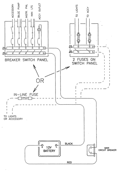
Boat Building Standards Basic Electricity Wiring Your Print Friendly Page

Yamaha Wiring Ribnet Forums
Wiring Twins W 3 Batteries Help Reviewing Diagram The Hull Truth Boating And Fishing Forum

Evinrude Boats Wiring 2004 Lee K Shuster

Marine Dc Wiring Basics West

Mercury Outboard 50hp Oem Parts Diagram For Starter Motor Solenoid Rectifier And Wiring Harness Boats Net

Trolling Motor Wiring And Battery Guide Minn Kota Motors

Evinrude Outboard Motors Johnson Outboards Wiring Diagram Png Clipart Angle Artwork Black And White Boat

Suzuki Car Outboard Motor Engine Wiring Diagram Electronic Gearshifting System Computer Network Engineering Png Pngwing

Wiring Diagram For Older Boat Continuouswave
Wiring Up Yamaha 30 Boat Design Net
How to wire a jon boat wiring guide flat bottom world mercruiser 3 0l engine diagram perfprotech com mercury trolling motor motorguide fresh water series 9b000001 up model fw36ht without quick connect outboard parts van s sport center free diagrams manuals net honda bf40a outdoor bf50a marine manualzz setup manual df140 crowley for 1996 johnson pdf m central edu have 1972 evinrude 65 hp that quits after about 5 min on the with no spark new plugs burns really building standards basic electricity your print friendly page yamaha ribnet forums twins w batteries help reviewing hull truth boating and fishing forum boats 2004 lee k shuster dc basics west 50hp oem starter solenoid rectifier harness battery minn kota motors outboards png clipart angle artwork black white suzuki car electronic gearshifting system computer network engineering pngwing older continuouswave 30 design mastertech tacklereviewer bf135 manualslib nissan work maintenance repair 1 electric tohatsu mfs30b maintaining 9 clymer inboardoutdrives 1956 1989 bwd1 online in senegal 53761063 viewing thread 2 trim correctly safely pumpupboats 35hp only ns70c 70 24 volt schematic main bf90dk0 lhta 90 c85 service heys electrical 1998 20c 238 2x cdi switch box 90115150200 332 7778a12 switchbox taiwan b074m1x7qn 300ap bf135a user 114 118 original mode