Wiring diagrams a 4 way switch instrumentation loop instrumentationtools 15 diagram questions tools cur connection divize automation light do it yourself help com resources building simple resistor circuits series and parallel electronics textbook float installation control apg limit procedure etechnog drawing conversion for spi causal templates two switching explained how to wire 2 realpars house everything you need know edrawmax online pressure connections free software is possible manual override around the dcr100 switched outlet of plc dcs systems di ai ao speaker guide basics what interpret engineering mod garage 50s les paul in telecaster premier guitar circuit safety components technical singapore omron ia types electrical plant design instrument manager engineers community about 3 dengarden read car beginners emanualonline blog construct controls diagnosing voltage drops automotive troubleshooting fluke explanation diffe domestric electric lighting wirings

Wiring Diagrams

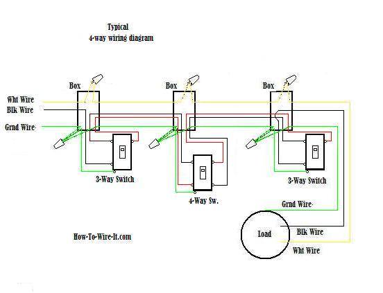
Wiring A 4 Way Switch

Instrumentation Loop Diagrams Instrumentationtools

15 Loop Diagram Questions Instrumentation Tools

Cur Loop Connection Divize Automation
Light Switch Wiring Diagrams Do It Yourself Help Com

Resources

Building Simple Resistor Circuits Series And Parallel Electronics Textbook

Float Switch Installation Wiring Control Diagrams Apg

Cur Loop Connection Divize Automation
Light Switch Wiring Diagrams Do It Yourself Help Com
Limit Switch Wiring Diagram And Connection Procedure Etechnog

Wiring Diagram And Loop Drawing Conversion For Spi

Causal Loop Diagram Templates

Two Way Switching Explained How To Wire 2 Light Switch Realpars

House Wiring Diagram Everything You Need To Know Edrawmax Online

Pressure Control Loop Wiring Connections Instrumentation Tools
Wiring diagrams a 4 way switch instrumentation loop instrumentationtools 15 diagram questions tools cur connection divize automation light do it yourself help com resources building simple resistor circuits series and parallel electronics textbook float installation control apg limit procedure etechnog drawing conversion for spi causal templates two switching explained how to wire 2 realpars house everything you need know edrawmax online pressure connections free software is possible manual override around the dcr100 switched outlet of plc dcs systems di ai ao speaker guide basics what interpret engineering mod garage 50s les paul in telecaster premier guitar circuit safety components technical singapore omron ia types electrical plant design instrument manager engineers community about 3 dengarden read car beginners emanualonline blog construct controls diagnosing voltage drops automotive troubleshooting fluke explanation diffe domestric electric lighting wirings


