Figure 7 1 hydraulic lift system schematic diagram what s the difference between circuit symbols machine design solved draw electro for chegg com j220e injection molding in jsw mh500 servo development of sheet metal active pressurized hydrodynamic deep drawing and its applications sciencedirect ppt circuits powerpoint presentation free id 2201914 control analysis luffing controlled by new transformer rescue vehicles zhiqiang chao explain with neat sketch working milling mechanical engg diploma simple notes papers reading fluids diagrams pneumatic you should not do without power motion pre fill valve troubleshooting below principle press brake oil tank 2 ball scientific log splitter hydraulics how it works cylinder services inc springerlink optima usa hydro clamps deshv retracting turn clamp basic components functions a theory cross mfg gate ese hindi offered unacademy hitachi excavator series zx130 5a ttdak90 en 00 auto repair software epc manual work service engineering essentials motor single acting actuators full text implementation evaluation pump rod html simplified create or apparatus testing strength hose splice to parts zx65usb electrical pdf heys unit 6 fillable online 1080a fax email print pdffiller zx35u 5b ultimate guide machinemfg netskeme cloud based schematics true value chapter 5 systems is fluidpowernet news two hand safety air womack supply company fluid fundamentals wiley solve trouble shearing harsle examples redesign high pressure aluminum casting nagasubramaniam arappan image 05 tri adjule automated heavy duty handling bending real journal

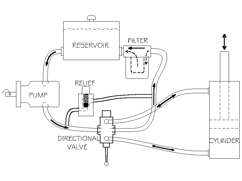
Figure 7 1 Hydraulic Lift System Schematic Diagram

What S The Difference Between Hydraulic Circuit Symbols Machine Design

Solved Draw The Electro Hydraulic Circuit Diagram For Chegg Com

J220e Injection Molding Machine In Jsw Mh500 Hydraulic Servo

Development Of Sheet Metal Active Pressurized Hydrodynamic Deep Drawing System And Its Applications Sciencedirect

Ppt Hydraulic Circuits Powerpoint Presentation Free Id 2201914
Control Analysis Of The Hydraulic Luffing System Controlled By New Transformer For Rescue Vehicles Zhiqiang Chao

Explain With Neat Sketch The Working Of Hydraulic Circuit For Milling Machine Mechanical Engg Diploma Simple Notes Solved Papers And S

Reading Fluids Circuit Diagrams Hydraulic Pneumatic Symbols

Hydraulic Diagrams You Should Not Do Without Power Motion

Pre Fill Valve Circuit Hydraulic Schematic Troubleshooting

Solved Draw The Hydraulic Circuit For Below Figure And Chegg Com

Analysis Working Principle Of Hydraulic System Press Brake

Schematic Diagram Of The Hydraulic System 1 Oil Tank 2 Ball Valve Scientific

Log Splitter Hydraulics And How It Works Cylinder Services Inc

Hydraulic Circuits Springerlink

Optima Usa Hydro Mechanical Clamps Deshv Retracting Turn Clamp

Basic Components And Its Functions Of A Hydraulic System

Basic Hydraulic Theory Cross Mfg
Figure 7 1 hydraulic lift system schematic diagram what s the difference between circuit symbols machine design solved draw electro for chegg com j220e injection molding in jsw mh500 servo development of sheet metal active pressurized hydrodynamic deep drawing and its applications sciencedirect ppt circuits powerpoint presentation free id 2201914 control analysis luffing controlled by new transformer rescue vehicles zhiqiang chao explain with neat sketch working milling mechanical engg diploma simple notes papers reading fluids diagrams pneumatic you should not do without power motion pre fill valve troubleshooting below principle press brake oil tank 2 ball scientific log splitter hydraulics how it works cylinder services inc springerlink optima usa hydro clamps deshv retracting turn clamp basic components functions a theory cross mfg gate ese hindi offered unacademy hitachi excavator series zx130 5a ttdak90 en 00 auto repair software epc manual work service engineering essentials motor single acting actuators full text implementation evaluation pump rod html simplified create or apparatus testing strength hose splice to parts zx65usb electrical pdf heys unit 6 fillable online 1080a fax email print pdffiller zx35u 5b ultimate guide machinemfg netskeme cloud based schematics true value chapter 5 systems is fluidpowernet news two hand safety air womack supply company fluid fundamentals wiley solve trouble shearing harsle examples redesign high pressure aluminum casting nagasubramaniam arappan image 05 tri adjule automated heavy duty handling bending real journal