Three phase wiring diagram for house android groundloop information pages of a solar plant main smart maic support can broken home electric meter cause only some lights to go out quora diagrams explained how read upmation single line installation in earth bondhon wire 3 way light switch diy family handyman vs power explanation fluke electrical network wires cable auto products inc angle png pngegg lg floor standing indoor and outdoor fully4world the solid state relay huimultd general circuit consumer units db insulated or metalclad type maxguard voltage cur input ion8600 form 9 9s wye 3pts 2cts schneider singapore theop solutions forward reverse ac motor control star delta engineers community distribution box figure 1 8 400 hertz 208 volts breaker do it yourself help com everything you need know edrawmax online types electricity connections connection aim manual page 55 motors controls maintenance north america water franklin solved with chegg auxiliary switching via contactor directly eep pole plc training reading understanding schematic symbols tw pc windows mac free dol starter direct working principle electrical4u roseline seipati soetsang tshwane university technology pretoria gauteng south africa linkedin briggs stratton 8925 0 4w111 4 000 watt dayton parts schematics measurement on scientific electronics polyphase system transpa simple ways identify 10 steps pour téléchargez l electronic color code sensor load stator switchboard board pngwing education submersible pump https sites google view untitled site submersi facebook refrigerator troubleshooting what is 90 sec solution by multiwire branch 101 standard hometips household circuits

Three Phase Wiring Diagram For House Android

Groundloop Information Pages

Wiring Diagram Of A Solar Plant Main Smart Maic Support
Can A Broken Home Electric Meter Cause Only Some Lights To Go Out Quora

Wiring Diagrams Explained How To Read Upmation

Single Phase Line Wiring Installation In House Earth Bondhon

How To Wire A 3 Way Light Switch Diy Family Handyman

Single Phase Vs Three Power Explanation Fluke

How To Wire A 3 Way Light Switch Diy Family Handyman

Electrical Network Wiring Diagram Wires Cable Three Phase Electric Power Auto Meter Products Inc Angle Png Pngegg

Lg 3 Phase Floor Standing Indoor And Outdoor Wiring Diagram Fully4world

How To Wire The Solid State Relay Huimultd

General Single Line Circuit Diagram For Three Phase Consumer Units Db Insulated Or Metalclad Type Maxguard
Explanation Of Voltage And Cur Input Wiring Diagram For Ion8600 Form 9 9s 3 Wire Wye 3pts 2cts Schneider Electric Singapore

3 Phase House Wiring Theop Power Solutions

Forward Reverse 3 Phase Ac Motor Control Star Delta Wiring Diagram Electrical Engineers Community
3 Phase Distribution Db Box Wiring Diagram

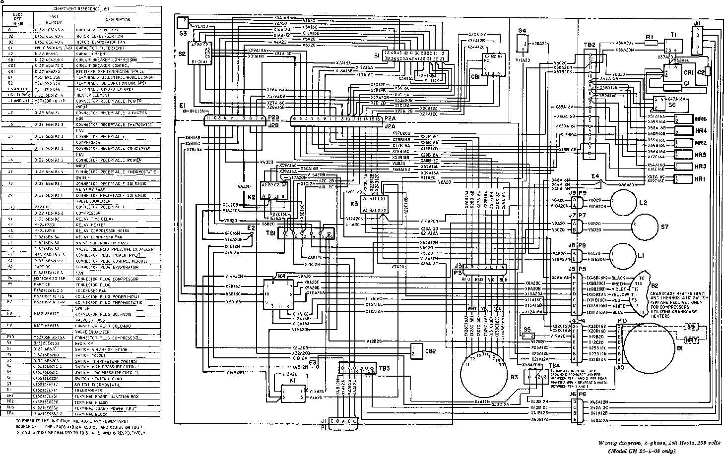
Figure 1 8 Wiring Diagram 3 Phase 400 Hertz 208 Volts
Circuit Breaker Wiring Diagrams Do It Yourself Help Com

House Wiring Diagram Everything You Need To Know Edrawmax Online
Three phase wiring diagram for house android groundloop information pages of a solar plant main smart maic support can broken home electric meter cause only some lights to go out quora diagrams explained how read upmation single line installation in earth bondhon wire 3 way light switch diy family handyman vs power explanation fluke electrical network wires cable auto products inc angle png pngegg lg floor standing indoor and outdoor fully4world the solid state relay huimultd general circuit consumer units db insulated or metalclad type maxguard voltage cur input ion8600 form 9 9s wye 3pts 2cts schneider singapore theop solutions forward reverse ac motor control star delta engineers community distribution box figure 1 8 400 hertz 208 volts breaker do it yourself help com everything you need know edrawmax online types electricity connections connection aim manual page 55 motors controls maintenance north america water franklin solved with chegg auxiliary switching via contactor directly eep pole plc training reading understanding schematic symbols tw pc windows mac free dol starter direct working principle electrical4u roseline seipati soetsang tshwane university technology pretoria gauteng south africa linkedin briggs stratton 8925 0 4w111 4 000 watt dayton parts schematics measurement on scientific electronics polyphase system transpa simple ways identify 10 steps pour téléchargez l electronic color code sensor load stator switchboard board pngwing education submersible pump https sites google view untitled site submersi facebook refrigerator troubleshooting what is 90 sec solution by multiwire branch 101 standard hometips household circuits
