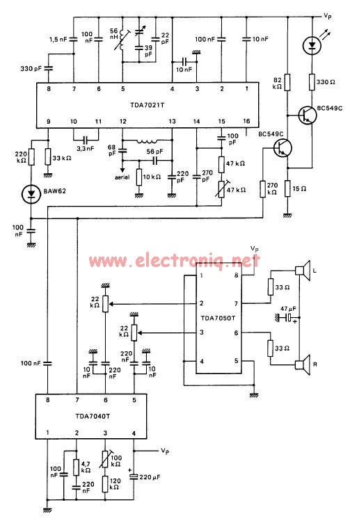
Fm Radio Receiver Schematic Circuit Diagram


Understanding the Fm Radio Receiver Schematic Circuit Diagram


When it comes to wiring diagrams, no two are the same. Sometimes, you may find a diagram that looks complex, but when you break it down, the pieces fit together perfectly. Other times, a diagram may look simple, but the connections are not so straightforward. The FM radio receiver schematic circuit diagram is one of those diagrams that looks complex but holds some interesting hidden features.

In this article, we will take a closer look at the FM radio receiver schematic circuit diagram and explain how the different components work together to create a functioning radio. We will explore various topics such as the FM signal, the antenna, amplifiers, and filters. By the end, you should have a better understanding of how a wiring diagram works, and how to wire up a radio receiver.

The FM Signal


FM radio signals are broadcast using a frequency modulation (FM) signal. This type of signal is modulated by an audio signal, which is then translated into an electrical signal. The electrical signal is transmitted from the broadcasting station to the receiver, where it is converted back into the audio signal. FM radio receivers are equipped with tuners that are able to tune in to a certain frequency and pick up the signal.

The FM signal is composed of several components. It includes the carrier wave, which carries the signal, along with the sidebands, which contain the audio information. The FM signal also has a modulation index, which describes the amount of variation of the signal and affects the quality of sound produced.

The Antenna


The antenna is an important part of any FM radio receiver. The antenna helps to capture the FM signal and convert it into electrical energy. It is usually made out of metal or a combination of metal and plastic. Depending on the type of radio receiver, antennas can be fixed or directional. Directional antennas help to focus the signal in a specific direction.

The antenna is connected to the receiver through a coaxial cable. This cable carries the signal from the antenna to the receiver. Coaxial cables come in various sizes and shapes, and it is important to make sure that the correct size is used for the receiver.

Amplifiers and Filters


The FM radio receiver contains amplifiers and filters to help strengthen the signal. The amplifiers increase the strength of the signal, while the filters help to reduce any interference or noise. The amplifiers are usually located inside the receiver, while the filters are placed between the antenna and the receiver.

The amplifiers and filters are connected to the receiver through a series of transistors and capacitors. These components help to control the flow of the signal and ensure that the signal is strong enough to be heard. The transistors and capacitors can also be adjusted to fine-tune the signal and reduce any interference.

Conclusion


Understanding the FM radio receiver schematic circuit diagram can seem overwhelming at first, but it is actually relatively simple when broken down. The components of the FM signal, the antenna, the amplifiers and filters, and the transistors and capacitors all work together to ensure that the signal is strong and free of interference. By understanding the basics of the diagram, you can wire up a radio receiver and receive a clear FM signal.


Circuit Zone Com Electronic Kits Projects Schematics Diy Electronics

Circuit Zone Com Electronic Kits Projects Schematics Diy Electronics


Digital Pll Controlled Fm Radio Circuit Tea5767 Receiver

Digital Pll Controlled Fm Radio Circuit Tea5767 Receiver


Vega Fm112 Am Fm Radio Receiver Sch Service Manual Schematics Eeprom Repair Info For Electronics Experts

Vega Fm112 Am Fm Radio Receiver Sch Service Manual Schematics Eeprom Repair Info For Electronics Experts


How To Build An Fm Radio Receiver Circuit Basics

How To Build An Fm Radio Receiver Circuit Basics


Simple Am Radio Receiver At Home Envirementalb Com

Simple Am Radio Receiver At Home Envirementalb Com


Usb Fm Transmitter Circuit

Usb Fm Transmitter Circuit


Tda7000 Fm Radio Circuit Electronics Projects Circuits

Tda7000 Fm Radio Circuit Electronics Projects Circuits


How To Build An Fm Radio Receiver Circuit Basics

How To Build An Fm Radio Receiver Circuit Basics


Simplest Am Radio Circuit Homemade Projects

Simplest Am Radio Circuit Homemade Projects


Schematic Diagram Ta8122 Am Fm Radio Receiver Circuit Under Repository Circuits 21213 Next Gr

Schematic Diagram Ta8122 Am Fm Radio Receiver Circuit Under Repository Circuits 21213 Next Gr


How To Build A Basic Am Or Fm Radio On Budget With Tools Quora

How To Build A Basic Am Or Fm Radio On Budget With Tools Quora


Radio And Communication Circuits Part 1

Radio And Communication Circuits Part 1


Fm Receiver Circuit Using Tda7021 Lm386

Fm Receiver Circuit Using Tda7021 Lm386


Am Radio Receiver With Three Bc548 Transistors

Am Radio Receiver With Three Bc548 Transistors


Small Fm Receiver

Small Fm Receiver


Am Radio Receiver A Schematic Circuit Diagram Of Scientific

Am Radio Receiver A Schematic Circuit Diagram Of Scientific


The Circuit Of A Simple Radio Receiver 9 Scientific Diagram

The Circuit Of A Simple Radio Receiver 9 Scientific Diagram


Pc Fm Radio Circuit

Pc Fm Radio Circuit


Results Page 5 About Varicap Fm Searching Circuits At Next Gr

Results Page 5 About Varicap Fm Searching Circuits At Next Gr


Super Circuit Diagram Simple Vhf Fm Aircraft Receiver

Super Circuit Diagram Simple Vhf Fm Aircraft Receiver