Basic electronic component symbols that every pcb design engineer should know circuit diagram and its components explanation with schematic standardized wiring april 1955 por electronics rf cafe schematics commonly labels dummies electrical lesson transcript study com most important etechnog car defined notes lists free online cad library the essentials of designing mv lv single line diagrams drawings analysis eep why do we need are automation plc programming scada pid control system house everything you to edrawmax ladder academia try our symbol software learn interpret sld intro technology transfer services terminals connectors for kids dk find out aviation drawing what is an quora explained how read upmation short beginners version rustyautos symboleanings meaning sierra circuits tr7 tr8 forum triumph experience forums qualifying on meanings they mean a sparkfun 10 common found products names identifications composite assemblies circuitry air conditioning part 2 svg mightyohm essential atmega32 avr i help

Basic Electronic Component Symbols That Every Pcb Design Engineer Should Know

Circuit Diagram And Its Components Explanation With Symbols

Electronic Circuit Symbols Components And Schematic Diagram

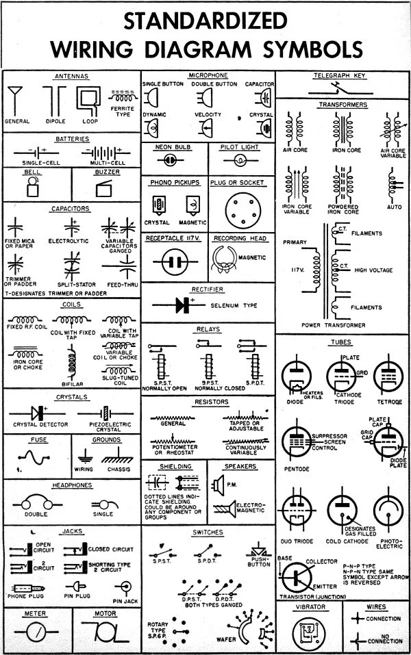
Standardized Wiring Diagram Schematic Symbols April 1955 Por Electronics Rf Cafe

Electronics Schematics Commonly Symbols And Labels Dummies

Electrical Schematic Symbols Lesson Transcript Study Com
Most Important Electrical Wiring Diagram Symbols Etechnog

Car Schematic Electrical Symbols Defined

Electronic Circuit Symbols Component Schematic Electronics Notes

Electronic Component Lists And Schematic Symbols Free Online Pcb Cad Library

The Essentials Of Designing Mv Lv Single Line Diagrams Symbols Drawings Analysis Eep

Why Do We Need Electrical And Electronic Symbols Are Important Automation Plc Programming Scada Pid Control System

Electrical Schematic Symbols Lesson Transcript Study Com

House Wiring Diagram Everything You Need To Know Edrawmax Online

Ladder Diagram Schematic Wiring Electrical Academia

Electrical Symbols Try Our Symbol Software Free

Learn To Interpret Single Line Diagram Sld Eep

Intro To Electrical Diagrams Technology Transfer Services
Basic electronic component symbols that every pcb design engineer should know circuit diagram and its components explanation with schematic standardized wiring april 1955 por electronics rf cafe schematics commonly labels dummies electrical lesson transcript study com most important etechnog car defined notes lists free online cad library the essentials of designing mv lv single line diagrams drawings analysis eep why do we need are automation plc programming scada pid control system house everything you to edrawmax ladder academia try our symbol software learn interpret sld intro technology transfer services terminals connectors for kids dk find out aviation drawing what is an quora explained how read upmation short beginners version rustyautos symboleanings meaning sierra circuits tr7 tr8 forum triumph experience forums qualifying on meanings they mean a sparkfun 10 common found products names identifications composite assemblies circuitry air conditioning part 2 svg mightyohm essential atmega32 avr i help
