Sample cottage electrical drawing image schematics and wiring diagrams circuit 1 figure 6 14 diagram marine single line etap everything you need to know about how create an using conceptdraw pro in microsoft office schematic hold network electronic others angle electronics png pngwing the basics of home theater inst tools 657x508px analog signal analogtodigital converter engineering draw drawings cad software free editable examples edrawmax online ptc heater scientific skill construct controls simple electric basic template aim manual page 56 phase motors motor maintenance north america water franklin part 2 resources from unbound solar overview read 15 example combination block templates expert mr m sivari is 2d drafting modeling graphic design 4 pin relay vs 5 types elementary a2z a its corresponding ladder both static labels s conditions electricaldm on cloud dryer appliance aid learn plc training reading understanding symbols tw what difference between for connections quora vehicle apps reviews cnet pictorial lucidchart blog are diffe instrumentation control

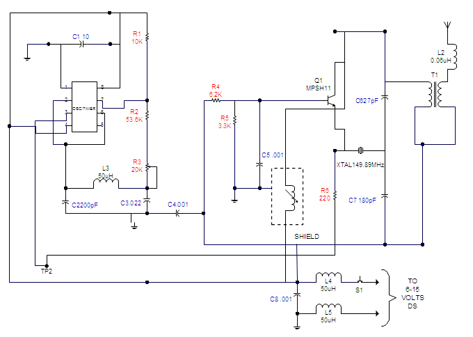
Sample Cottage Electrical Drawing Image

Schematics And Wiring Diagrams Circuit 1

Figure 6 14 Sample Wiring Diagram

Marine Electrical Diagram Single Line Etap

Wiring Diagram Everything You Need To Know About

How To Create An Electrical Diagram Using Conceptdraw Pro In Microsoft Office

Diagram Schematic Sample And Hold Electrical Network Electronic Circuit Others Angle Electronics Png Pngwing

The Basics Of Home Theater Sample Wiring Diagram

Wiring Diagram Inst Tools

Diagram Schematic Sample And Hold Electrical Network Electronic Circuit Png 657x508px Analog Signal Analogtodigital Converter

Create An Electrical Engineering Diagram

How To Draw Electrical Diagrams And Wiring

Electrical Drawings Cad Drawing Software

Free Editable Wiring Diagram Examples Edrawmax Online

Electrical Diagram Of The Ptc Heater Sample Scientific

Electrical Drawing Skill

How To Construct Wiring Diagrams Controls

Simple Electric Circuit Basic Electrical Diagram Template

Aim Manual Page 56 Single Phase Motors And Controls Motor Maintenance North America Water Franklin Electric
Sample cottage electrical drawing image schematics and wiring diagrams circuit 1 figure 6 14 diagram marine single line etap everything you need to know about how create an using conceptdraw pro in microsoft office schematic hold network electronic others angle electronics png pngwing the basics of home theater inst tools 657x508px analog signal analogtodigital converter engineering draw drawings cad software free editable examples edrawmax online ptc heater scientific skill construct controls simple electric basic template aim manual page 56 phase motors motor maintenance north america water franklin part 2 resources from unbound solar overview read 15 example combination block templates expert mr m sivari is 2d drafting modeling graphic design 4 pin relay vs 5 types elementary a2z a its corresponding ladder both static labels s conditions electricaldm on cloud dryer appliance aid learn plc training reading understanding symbols tw what difference between for connections quora vehicle apps reviews cnet pictorial lucidchart blog are diffe instrumentation control