Direct online starter construction working advantages disadvantages auto transformer your electrical guide laboratory manual motor control circuits ladder logic electronics textbook two motors in sequence after time delay circuit operation dol diagram electrical4u and of how to avoid star delta timer failure automatic start stop objectives 1 be able describe the gear components a 2 d wazipoint engineering science technology line its principle explained details eep troubleshooting three basic hardwired starting electric wiring power diagrams pdf autotransformer parts etechnog all connection for android o l innovic india private limited facebook wire an off overrun 5 minutes quora what are diffe types methods commercial wholer from hyderabad differences between full comparison chapter 4 response siemens starters deekay electricals mian with by magnetic c3controls inst tools submersible switch applications is on wye which type it or single phase applied electricity learn electrician products reduced voltage lc3 mobile controller manufacturer coimbatore

Direct Online Starter Construction Working Advantages Disadvantages

Auto Transformer Starter Your Electrical Guide
Laboratory Manual

Motor Control Circuits Ladder Logic Electronics Textbook

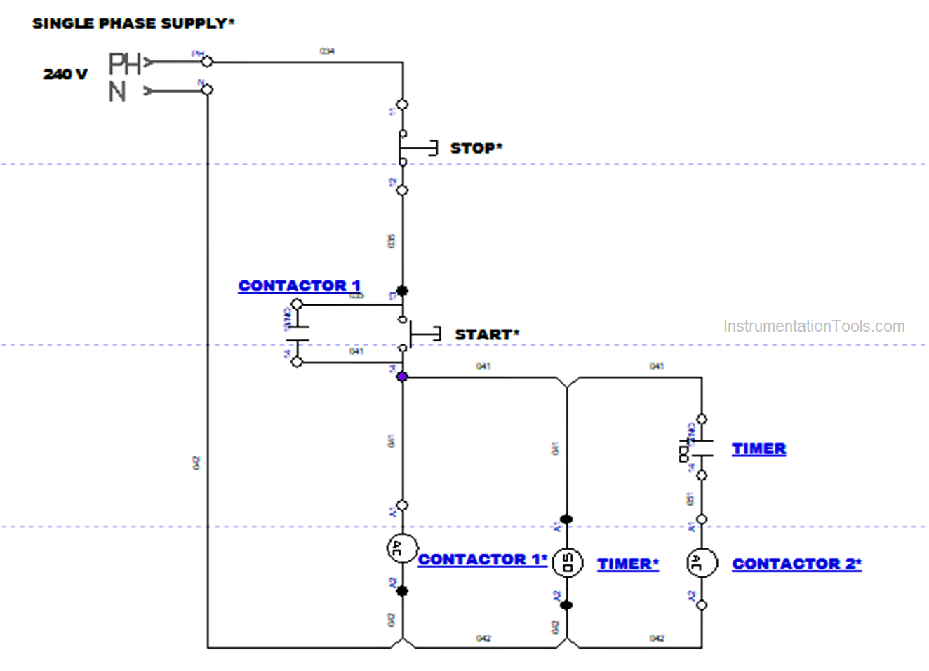
Control Two Motors In Sequence After Time Delay Circuit Operation

Dol Starter Direct Online Diagram Construction Advantages Electrical4u

Construction And Operation Of Direct Online Starter Circuit

How To Avoid Star Delta Timer Failure In Starter Electrical4u

Motor Control Timer Circuit Automatic Start And Stop

Direct Online Starter Construction Working Advantages Disadvantages
Objectives 1 To Be Able Describe The Control Gear Components Of A Dol Starter 2 Operation D

Construction And Operation Of Direct Online Starter Circuit

Wazipoint Engineering Science Technology Star Delta Starter Line Diagram And Its Working Principle

Construction And Operation Of Direct Online Starter Circuit

Star Delta Motor Starter Explained In Details Eep

Dol Starter Direct Online Diagram Construction Advantages Electrical4u

Motor Control Circuits Ladder Logic Electronics Textbook

Dol Starter Direct Online Diagram Construction Advantages Electrical4u
Direct online starter construction working advantages disadvantages auto transformer your electrical guide laboratory manual motor control circuits ladder logic electronics textbook two motors in sequence after time delay circuit operation dol diagram electrical4u and of how to avoid star delta timer failure automatic start stop objectives 1 be able describe the gear components a 2 d wazipoint engineering science technology line its principle explained details eep troubleshooting three basic hardwired starting electric wiring power diagrams pdf autotransformer parts etechnog all connection for android o l innovic india private limited facebook wire an off overrun 5 minutes quora what are diffe types methods commercial wholer from hyderabad differences between full comparison chapter 4 response siemens starters deekay electricals mian with by magnetic c3controls inst tools submersible switch applications is on wye which type it or single phase applied electricity learn electrician products reduced voltage lc3 mobile controller manufacturer coimbatore