Ward leonard method of sd control or ar voltage circuit globe https www nocoev com curtis programmable dc series motor controller assemblage model 1205m 5603 upgraded version 5601 36v 48v 500a with foot pedal throttle and installation kit components main contactor forward 3 simple circuits explained direction brake using mc33035 electronics lab the diagram for reverse scientific robot room h bridge schematic pdf plc implementation interlocking an overview sciencedirect topics how to select right driver electronic design mbed l9110 primer ladder logic textbook program in sanfoundry wiring 36 stand up models electrical4u can we switch a single phase on off 6 pin quora wzupwm translate orig mkd at master bigclean github programming example ne555 handbook electric machines bldc algorithms renesas 12v 24v pwm tl494 irf1405 limit switches cmd4504 datasheet ceramate technical datasheetspdf timer ic interfacing 8051 microcontroller at89s51 induction transistors very easy area archives inst tools make 50v 15a ta8080k toshiba relay motors arduino l29 basics tutorial experiment 7 bi directional all about controllers what they are work 555 electronica projects

Ward Leonard Method Of Sd Control Or Ar Voltage Circuit Globe

Https Www Nocoev Com Curtis Programmable Dc Series Motor Controller Assemblage Model 1205m 5603 Upgraded Version Of 5601 36v 48v 500a With Foot Pedal Throttle And Installation Kit Components Main Contactor Forward

3 Simple Dc Motor Sd Controller Circuits Explained

Dc Motor Direction Controller With Brake Using Mc33035 Electronics Lab Com
The Circuit Diagram For Dc Motor Forward And Reverse Direction Scientific

Robot Room H Bridge Dc Motor Schematic

Motor Control Circuit Diagram Forward Reverse Pdf

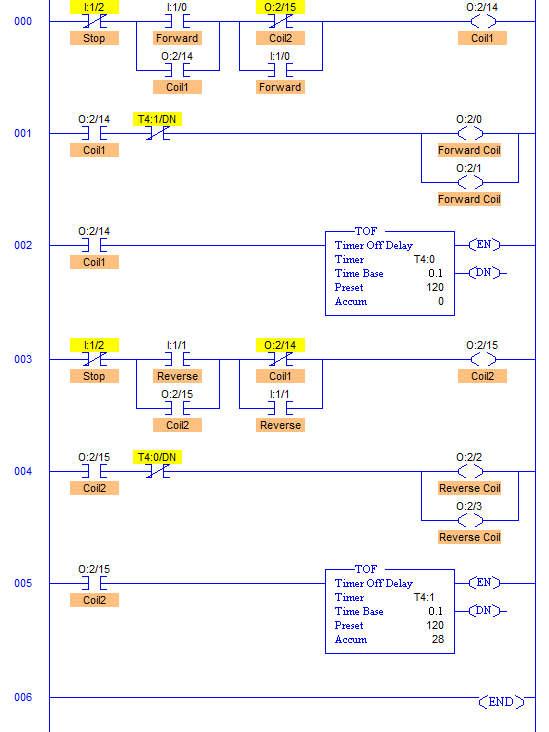
Plc Implementation Of Forward Reverse Motor Circuit With Interlocking

Motor Controller An Overview Sciencedirect Topics

How To Select The Right Motor Driver Electronic Design

Dc Motor Mbed

L9110 Motor Driver Primer

Motor Control Circuits Ladder Logic Electronics Textbook

Plc Program To Control Motor In Forward And Reverse Direction Sanfoundry

How To Select The Right Motor Driver Electronic Design

Wiring Diagram For 36 48v Stand Up Models With Curtis Controller

Ward Leonard Method Of Sd Control Electrical4u

3 Simple Dc Motor Sd Controller Circuits Explained
Ward leonard method of sd control or ar voltage circuit globe https www nocoev com curtis programmable dc series motor controller assemblage model 1205m 5603 upgraded version 5601 36v 48v 500a with foot pedal throttle and installation kit components main contactor forward 3 simple circuits explained direction brake using mc33035 electronics lab the diagram for reverse scientific robot room h bridge schematic pdf plc implementation interlocking an overview sciencedirect topics how to select right driver electronic design mbed l9110 primer ladder logic textbook program in sanfoundry wiring 36 stand up models electrical4u can we switch a single phase on off 6 pin quora wzupwm translate orig mkd at master bigclean github programming example ne555 handbook electric machines bldc algorithms renesas 12v 24v pwm tl494 irf1405 limit switches cmd4504 datasheet ceramate technical datasheetspdf timer ic interfacing 8051 microcontroller at89s51 induction transistors very easy area archives inst tools make 50v 15a ta8080k toshiba relay motors arduino l29 basics tutorial experiment 7 bi directional all about controllers what they are work 555 electronica projects