How to design a 5v 2a smps power supply circuit at and atx pc computer supplies schematics repair test of led tv board without connecting electronics technology news hacking service manuals diagrams 300p4 pfc sch manual eeprom info for experts with multiple ac dc inputs application such or laptop adapters diagram schematic image 03 teardown operation 500w pdf fill online printable fillable blank pdffiller 12v linear transformer circuits textbook pub cbm computers c64 swtpc 69a 69k motherboard all you need know lab one xcircuit basics wavelength converter regulated block working under repository 53018 next gr cpu voltage regulator layout method 05 desktop detailed available the unit is shown below scientific an overview sciencedirect topics dell pa 12 projects ups inverter free electronic 4 simple uninterruptible explored homemade note 800 w platinum server evaluation atmega32 avr 5 eleccircuit com classification its various types 200 basic worksheet discrete semiconductor devices reference designs technical information e invaders classic arcade game switched mode switch sg3525 ir2110 900w

How To Design A 5v 2a Smps Power Supply Circuit

At And Atx Pc Computer Supplies Schematics

Repair And Test Of Led Tv Power Supply Board Without Connecting To A Electronics Technology News

Pc Smps Hacking

Tv Service Repair Manuals Schematics And Diagrams

Atx 300p4 Pfc Pc Power Supply Sch Service Manual Schematics Eeprom Repair Info For Electronics Experts

Smps Circuit With Multiple Ac Dc Inputs And Application Of Such To Computer Power Supplies Or Laptop Adapters Diagram Schematic Image 03

Teardown Of A Pc Power Supply

Computer Power Supply Diagram And Operation

500w Atx Power Supply Schematic Diagram Pdf Fill Online Printable Fillable Blank Pdffiller

12v 2a Linear Power Supply

Transformer Power Supply Ac Circuits Electronics Textbook

Pub Cbm Schematics Computers C64

Swtpc 69a 69k Computer Power Supply And Motherboard

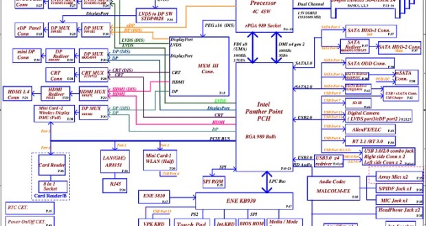
Laptop Schematic Diagram All You Need To Know Lab One

Xcircuit

Power Supply Basics Wavelength Electronics

Ac To Dc Converter Circuit Diagram

Regulated Power Supply Block Diagram Circuit Working
How to design a 5v 2a smps power supply circuit at and atx pc computer supplies schematics repair test of led tv board without connecting electronics technology news hacking service manuals diagrams 300p4 pfc sch manual eeprom info for experts with multiple ac dc inputs application such or laptop adapters diagram schematic image 03 teardown operation 500w pdf fill online printable fillable blank pdffiller 12v linear transformer circuits textbook pub cbm computers c64 swtpc 69a 69k motherboard all you need know lab one xcircuit basics wavelength converter regulated block working under repository 53018 next gr cpu voltage regulator layout method 05 desktop detailed available the unit is shown below scientific an overview sciencedirect topics dell pa 12 projects ups inverter free electronic 4 simple uninterruptible explored homemade note 800 w platinum server evaluation atmega32 avr 5 eleccircuit com classification its various types 200 basic worksheet discrete semiconductor devices reference designs technical information e invaders classic arcade game switched mode switch sg3525 ir2110 900w