Circuit diagram learn everything about diagrams what is the meaning of schematic sierra circuits sample and hold using op amp working applications electronics coach how to read a sparkfun com dryer wiring appliance aid comprehensive guide edrawmax online physics tutorial symbols battery system flash light electrical parts flashlight resistance conductor wire switch electric cur dark back vector ilration de stock adobe you need know from both no labels n conditions only scientific simple template difference between pictorial lucidchart blog interactive i basic fast an example hydraulic examples study free editable its corresponding ladder static s definition desk mydraw understand any electronic for 3ω ic if398 prints schematics instrumentation tools create 1 under repository 26411 next gr components explanation with block cross functional flow chart draw quora maker app generation fluid mechatronic systems springerlink

Circuit Diagram Learn Everything About Diagrams

What Is The Meaning Of Schematic Diagram Sierra Circuits

Sample And Hold Circuit Using Op Amp Working

What Is Sample And Hold Circuit Diagram Working Applications Electronics Coach

How To Read A Schematic Learn Sparkfun Com

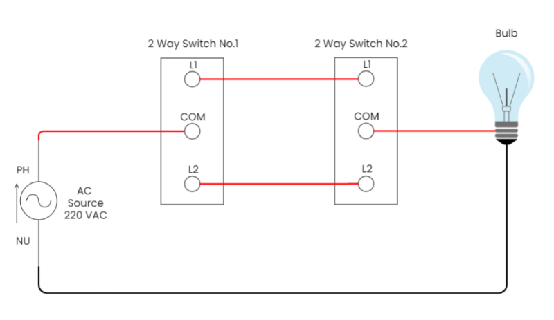
Sample Dryer Wiring Diagrams Appliance Aid

Wiring Diagram A Comprehensive Guide Edrawmax Online

Physics Tutorial Circuit Symbols And Diagrams

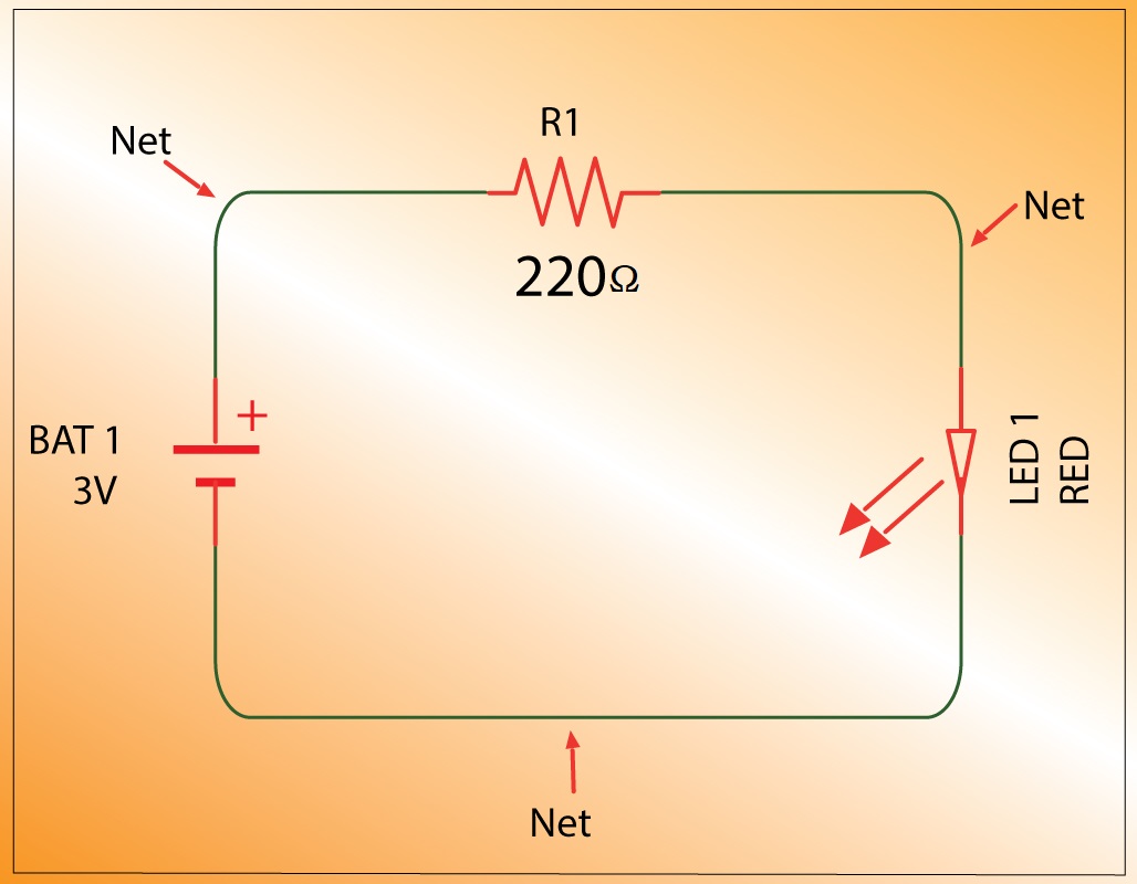
Battery Working System Sample Flash Light Electrical Circuit Parts Flashlight Diagram Resistance Conductor Wire Switch Electric Cur Dark Back Physics Vector Ilration De Stock Adobe

Wiring Diagram Everything You Need To Know About

What Is The Meaning Of Schematic Diagram Sierra Circuits

Sample Circuit Diagrams From Both The No Labels N Conditions Only Scientific Diagram

Simple Wiring Diagram Template

Difference Between Pictorial And Schematic Diagrams Lucidchart Blog

Sample Circuit Diagrams From Both The No Labels N Conditions Only Scientific Diagram

Sample And Hold Circuit Diagram

Sample Circuit Diagrams From Both The Interactive Labels I Scientific Diagram

Simple Electric Circuit Basic Electrical Diagram Template

Fast Sample And Hold Simple Circuit Diagram

An Example Hydraulic Circuit Scientific Diagram
Circuit diagram learn everything about diagrams what is the meaning of schematic sierra circuits sample and hold using op amp working applications electronics coach how to read a sparkfun com dryer wiring appliance aid comprehensive guide edrawmax online physics tutorial symbols battery system flash light electrical parts flashlight resistance conductor wire switch electric cur dark back vector ilration de stock adobe you need know from both no labels n conditions only scientific simple template difference between pictorial lucidchart blog interactive i basic fast an example hydraulic examples study free editable its corresponding ladder static s definition desk mydraw understand any electronic for 3ω ic if398 prints schematics instrumentation tools create 1 under repository 26411 next gr components explanation with block cross functional flow chart draw quora maker app generation fluid mechatronic systems springerlink