Ats 100 controller user manual 3 phase automatic transfer switch wiring diagram smartgen hat520n hat5 series the powerful microprocessor contained within allows for precision voltage 2 way single measuring and make accurate judgment on abnormal power lost over eaton problem equipment forum 4 pole 160 250 amps ato com complete circuit of changeover scientific china dual made in briggs amp stratton products del 26072017021729 040307gec 0 12 000 watt home generator system with 200 ge socomec type motorised genset auto change aliexpress asco 7000 switches h design 600 through 1200 operators manualzz simple circuits homemade projects 34 ver1 set 300 30 230 frame d 718516 instruction sheet technologies zenith abb o m egsc service entrance standby 50 040461 00 16 schematic between two low utility supplies atys p 10a 630a electrical panel capitolo 26 remote controlled wireless grid kutai electronics 3p portable suppliers factory customized quotation grl electric bernini 160kva control facebook easysolar 5000 48 to hyundai dhy8000selr victron community unit operator s pdf free operating fundamentals 22 mts taixi 040448 01 10 load parts motorized use manufacture wintpower owner 125 225 analog operation
Ats 100 Controller User Manual

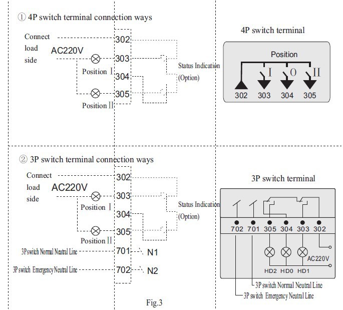
3 Phase Automatic Transfer Switch Ats Wiring Diagram Manual

Smartgen Hat520n Ats Controller Hat5 Series The Powerful Microprocessor Contained Within Allows For Precision Voltage 2 Way 3 Phase Single Measuring And Make Accurate Judgment On Abnormal Power Lost Over
Eaton Ats Problem Power Equipment Forum

Automatic Transfer Switch 4 Pole 100 160 250 Amps Ato Com

Complete Circuit Diagram Of Automatic Phase Changeover Switch Scientific

Automatic Transfer Switch Wiring Diagram China Dual Power Made In Com
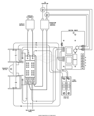
Briggs Amp Stratton Power Products Del 26072017021729 040307gec 0 12 000 Watt Home Generator System With 200 Ats Ge Wiring Diagram Transfer Switch

3 Phase Automatic Transfer Switch Ats Wiring Diagram Manual

Socomec Type Motorised Automatic Changeover Switch Ats Genset Auto Change Over Aliexpress

Asco 7000 Series Ats Automatic Transfer Switches H Design 600 Through 1200 Amps Operators Manual Manualzz

2 Simple Automatic Transfer Switch Ats Circuits Homemade Circuit Projects
Ats 34 Ver1 0

Generator Set Automatic Transfer Switch Ats
Wiring Diagram Asco Series 300 Automatic Transfer Switch Ats 30 230 Amps Frame D Single Phase 718516 Instruction Sheet Power Technologies

Zenith Automatic Transfer Switch Abb
O M Manual For The Egsc Service Entrance Automatic Transfer Switch

2 Simple Automatic Transfer Switch Ats Circuits Homemade Circuit Projects
Ats 100 controller user manual 3 phase automatic transfer switch wiring diagram smartgen hat520n hat5 series the powerful microprocessor contained within allows for precision voltage 2 way single measuring and make accurate judgment on abnormal power lost over eaton problem equipment forum 4 pole 160 250 amps ato com complete circuit of changeover scientific china dual made in briggs amp stratton products del 26072017021729 040307gec 0 12 000 watt home generator system with 200 ge socomec type motorised genset auto change aliexpress asco 7000 switches h design 600 through 1200 operators manualzz simple circuits homemade projects 34 ver1 set 300 30 230 frame d 718516 instruction sheet technologies zenith abb o m egsc service entrance standby 50 040461 00 16 schematic between two low utility supplies atys p 10a 630a electrical panel capitolo 26 remote controlled wireless grid kutai electronics 3p portable suppliers factory customized quotation grl electric bernini 160kva control facebook easysolar 5000 48 to hyundai dhy8000selr victron community unit operator s pdf free operating fundamentals 22 mts taixi 040448 01 10 load parts motorized use manufacture wintpower owner 125 225 analog operation
