Understanding the Basics of 27 MHz Transmitter And Receiver Circuit Diagrams
27 MHz transmitter and receiver circuits are essential components for everyday activities in the electronics world. They are widely used and proven to be reliable when it comes to broadcasting and receiving signals. The technology is so efficient that it is also making its way into the industrial environment. Understanding how it works and what components are necessary to build a transmitter and receiver circuit can give you the edge in building your own machines and gadgets.
A diagram is a must-have document when it comes to understanding any type of circuit. Its purpose is to provide a visual representation of the electrical elements and connect them together in the right order. Such diagrams are normally regarded as the basis of an electronics project and originate from the circuit designer. They aid in identifying existing errors and serve as a “map” for troubleshooting.
The Wiring Diagrams of 27 MHz Transmitter And Receiver Circuits
Wiring diagrams are schematic representations of the physical connection between components, including transistors, capacitors, resistors, diodes, and integrated circuits. The symbols that make up all wiring diagrams are standardized, meaning that, no matter what device you're dealing with, there will always be the same symbol for a certain electrical element. This makes it easier to understand the components used in the circuit and locate them on the board.
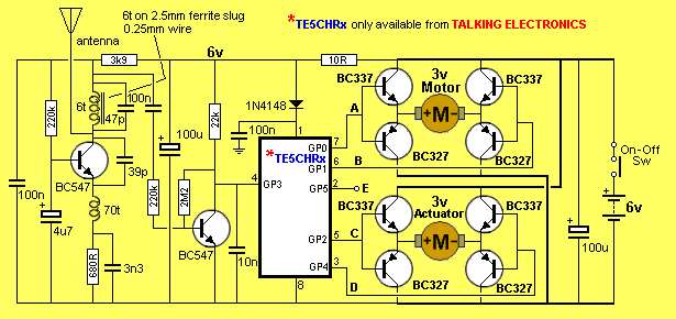
When it comes to 27 MHz transmitter and receiver circuits, wiring diagrams are essential for assembling them correctly. They contain all the parts of the circuitry, including the antenna, power sources, receivers, connectors, and more. The diagrams provide all the details you need to understand how each component connects, allowing you to solder the parts accurately. Although the core principles of these circuits remain the same, some specific components will vary in every application.
Components and Connections of 27 MHz Transmitter And Receiver Circuits
A 27 MHz transmitter and receiver circuit requires several components to function properly. The primary components are a power source, a transmitter, a receiver, and the antenna. The power source is used to power up the circuit, while the transmitter is responsible for sending out the signal. The signal then needs to be received by the receiver, which is connected to the antenna, which captures the signal and transmits it to the receiver. A connector is usually used to connect these components, as well as the other necessary elements in the circuit.
In order to make sure that these components are correctly connected, one should take a look at the wiring diagrams provided by the manufacturer. The diagrams will show exactly how each component is connected and how the connection is made. This is a crucial step, as it ensures that the circuit functions properly and that no damage can be caused due to improper connections.
Conclusion: Understanding 27 MHz Transmitter And Receiver Circuit Diagrams
Understand the basics of 27 MHz transmitter and receiver circuit diagrams is essential for anyone looking to build their own circuits. With the help of wiring diagrams, you'll be able to easily identify the components and make connections that will keep your circuit running smoothly. Make sure you always consult the diagrams provided by the manufacturer before you make any connections. With this knowledge, you'll be able to assemble and troubleshoot your own circuits with ease.

Nbfm 27mhz Transmitter Circuit
Bang 4ch Rc Remote Control 27mhz Circuit Pcb Transmitter And Receiver Board With Antenna Radio Sho Philippines

Remote Controlled Toy Car Demystified Full Electronics Project

Rf Schematics

Help With Rf Transformer All About Circuits

5 Channel Radio Remote Control Circuit Based Of Tx 2b Rx Pair

Design For A Radio Controlled Car Planet Analog
2ch Rc Remote Control 27mhz Circuit Pcb Transmitter And Receiver Board Radio System With Antenna Set Sho Malaysia
27mhz Links

27mhz Links

Cb 27mhz Transmitter Circuit

27mhz 2ch Remote Controller Receiver Transmitter Board With Antenna At Affordable S Free Shipping Real Reviews Photos Joom
27091tx 27 Mhz Remote Control Transmitter Schematics Ie Toys Hong Kong

49 Mhz Transmitter And Receiver 55 Off Barsauvage Com

Ljc2200 Infrared Ultrasonic And Radio Remote Control Receiver Circuit Diagram Seekic Com

27mhz 4ch Remote Control Circuit Board Pcb Transmitter Receives Antenna Toys S Reviews Zoodmall

27mhz Cb Band Circuit

27mhz Images For Free

27mhz Remote Control Range Hot 50 Off Www Ingeniovirtual Com