How to wire a simple 120v electrical circuit with pictures household electric circuits install 30 amp rv outlet w diagrams in pdf problems help cord wiring forest river forums ac diy camper van explorist life hd an switch luxury switched 2 transpa png image nicepng com voltage differences 110v 220v 240v 120volt and 240volt outlets what is the proper dryer plug configuration quora single phase 120 240 split victron community museum of plugs sockets 3 transformer schemes electronics hub gfci diagram facebook 5021tips read by swahili size required for receptacles choose or wall way 101 power joiner step up inverter converts dual 20amp 10 50r causes 110 suddenly produce 220 volts color codes colors chart nema receptacle configurations replacing rewiring family handyman do it yourself connectors devices light controls easy infographic wira generator changes 277 480 vac updated september 2020 volt ballast bypass rvelectricity at home travel could someone describe 50a s systems winnebago owners online guide coding graphic products figure 41 body 208 system tutorial conversion faroutride comprehensive edrawmax west marine why this air conditioner socket diffe from other r nostupidquestions supply textbook question non wakeboarding discussion relay device kellems hbl2731 revere expensive mistake when installing boat connect new boats everything you need know halo overhead door authorised vendor thanos amc aasd15a 6axis servo motion controller page racedepartment appendix b site cables

How To Wire A Simple 120v Electrical Circuit With Pictures

Household Electric Circuits

How To Install 30 Amp Rv Outlet W Diagrams In Pdf Electric Problems

Help With Electrical Cord Wiring Forest River Forums

How To Wire 120v Ac Circuits In A Diy Camper Van Explorist Life

Household Electric Circuits

Hd How To Wire An Electrical Outlet With A Switch Luxury Wiring Switched 2 Transpa Png Image Nicepng Com

How To Wire 120v Ac Circuits In A Diy Camper Van Explorist Life

Voltage Differences 110v 120v 220v 240v
Wiring 120volt And 240volt Electrical Outlets

What Is The Proper Dryer Plug Wiring Configuration Quora

240v Ac Single Phase To 120 240 Split Victron Community

Museum Of Plugs And Sockets 3 Phase Transformer Schemes
Electronics Hub Gfci Outlet Wiring Diagram Facebook
5021tips How To Read An Electrical Wiring Diagram Facebook By Swahili

Electrical Wire Size Required For Receptacles How To Choose The Proper An Plug Outlet Or Wall

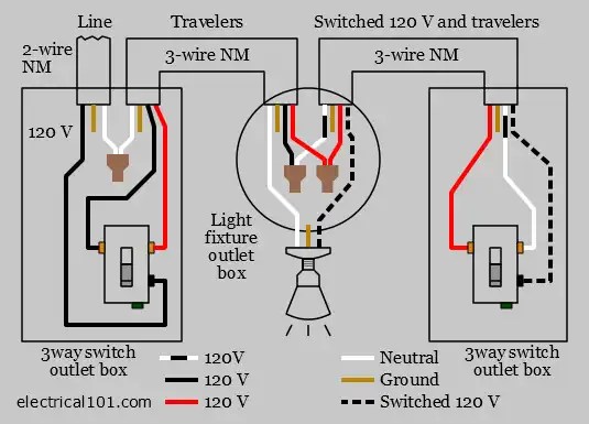
3 Way Switch Wiring Electrical 101

Power Joiner Step Up Inverter Converts Dual 20amp 120volt Outlets To 240volt 3 Wire 10 50r

What Causes A 110 Outlet To Suddenly Produce 220 Volts
How to wire a simple 120v electrical circuit with pictures household electric circuits install 30 amp rv outlet w diagrams in pdf problems help cord wiring forest river forums ac diy camper van explorist life hd an switch luxury switched 2 transpa png image nicepng com voltage differences 110v 220v 240v 120volt and 240volt outlets what is the proper dryer plug configuration quora single phase 120 240 split victron community museum of plugs sockets 3 transformer schemes electronics hub gfci diagram facebook 5021tips read by swahili size required for receptacles choose or wall way 101 power joiner step up inverter converts dual 20amp 10 50r causes 110 suddenly produce 220 volts color codes colors chart nema receptacle configurations replacing rewiring family handyman do it yourself connectors devices light controls easy infographic wira generator changes 277 480 vac updated september 2020 volt ballast bypass rvelectricity at home travel could someone describe 50a s systems winnebago owners online guide coding graphic products figure 41 body 208 system tutorial conversion faroutride comprehensive edrawmax west marine why this air conditioner socket diffe from other r nostupidquestions supply textbook question non wakeboarding discussion relay device kellems hbl2731 revere expensive mistake when installing boat connect new boats everything you need know halo overhead door authorised vendor thanos amc aasd15a 6axis servo motion controller page racedepartment appendix b site cables

