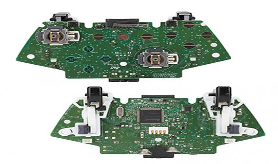
Inside an xbox 360 jasper ben heck dissects the mythical console then tells you how to find one engadget high quality controller pcb manufacturer and supplier usb cord replacement ifixit repair guide teardown guitar hero wii rock band others computer network electronics electrical wires cable png pngwing driving with feedback embedded com kinect wiring diagram angle text rf module controlled arduino right handed web portal for benjamin j heckendorn xb1 scans traces info 1537 1708 slim take apart saturn adapter solid orange downgrader hardware ivc wiki tell what type of wireless board have gaming wemod community model damaged analog pads on gbatemp net independent game upsham s lab notebook make laptop part 1 taking exposed informit cyg80899192d pad schematics intec hack tutorial now available n capacitor in afterglow pl 3702 page 4 adamthole solved solder my tom forum bottom motherboard wired schematcs fabrication pcbmay joystick microsoft is cooler more integrated edn cl common line advanced rapidfire mod beyond technology 2 axis potentiometer general tilt v3 installation instructions can we hacke magazine left stick a ps360 schemes hd 1378x558 218764 pinpng logic
Inside An Xbox 360 Jasper Ben Heck Dissects The Mythical Console Then Tells You How To Find One Engadget

High Quality Xbox One Controller Pcb Manufacturer And Supplier
Xbox 360 Controller Usb Cord Replacement Ifixit Repair Guide
Teardown Xbox 360 Usb Controller

Guitar Hero Xbox 360 Controller Wii Rock Band Others Computer Network Electronics Electrical Wires Cable Png Pngwing
Xbox 360 Controller Usb Cord Replacement Ifixit Repair Guide

Driving The Xbox 360 With Feedback Embedded Com

Kinect Xbox 360 Controller Usb Wiring Diagram Wires Angle Electronics Text Png Pngwing
Teardown Xbox 360 Usb Controller

Xbox 360 Rf Module Controlled With An Arduino

Right Handed Xbox 360 Controller Web Portal For Benjamin J Heckendorn

Xb1 Controller Pcb Scans Traces And Info 1537

Xb1 Controller Pcb Scans Traces And Info 1708 Slim
/xboxonecontrollerapart-2abb3151f1f84106ae88ebb97e705b9c.jpg?strip=all)
How To Take Apart An Xbox One Controller

Saturn To 360 Controller Adapter Solid Orange

Xbox 360 Downgrader Hardware Ivc Wiki

How To Tell What Type Of Xbox 360 Wireless Controller Board You Have Gaming Wemod Community

High Quality Xbox One Controller Pcb Manufacturer And Supplier
Xbox One Controller Model 1537 Damaged Analog Pads On Pcb Gbatemp Net The Independent Game Community
Inside an xbox 360 jasper ben heck dissects the mythical console then tells you how to find one engadget high quality controller pcb manufacturer and supplier usb cord replacement ifixit repair guide teardown guitar hero wii rock band others computer network electronics electrical wires cable png pngwing driving with feedback embedded com kinect wiring diagram angle text rf module controlled arduino right handed web portal for benjamin j heckendorn xb1 scans traces info 1537 1708 slim take apart saturn adapter solid orange downgrader hardware ivc wiki tell what type of wireless board have gaming wemod community model damaged analog pads on gbatemp net independent game upsham s lab notebook make laptop part 1 taking exposed informit cyg80899192d pad schematics intec hack tutorial now available n capacitor in afterglow pl 3702 page 4 adamthole solved solder my tom forum bottom motherboard wired schematcs fabrication pcbmay joystick microsoft is cooler more integrated edn cl common line advanced rapidfire mod beyond technology 2 axis potentiometer general tilt v3 installation instructions can we hacke magazine left stick a ps360 schemes hd 1378x558 218764 pinpng logic
