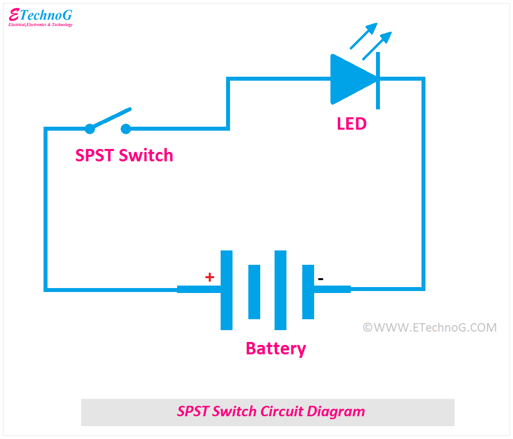
Wiring Diagram For Double Pole Single Throw Switch


Understanding the Wiring Diagram for a Double Pole Single Throw Switch


To ensure that your electronic systems are up to code and functioning properly, understanding a wiring diagram for a double pole single throw (DPST) switch is essential. A DPST switch is often used to control large appliances such as electric ovens or stoves, water heaters, and air conditioners. It works by connecting two circuits simultaneously, meaning it can turn both circuits on and off at the same time. This article will provide an overview of the wiring diagram for a DPST switch so you can better understand how it works.

A wiring diagram is a visual representation of the electrical components in a system and how they are connected. It shows the components, their various functions, and how they should be wired together. A wiring diagram typically includes information such as a schematic diagram, connector pinouts, and color codes. This helps make it easier to identify specific parts and troubleshoot problems.

Common Components in a Wiring Diagram


Wiring diagrams can vary in complexity depending on the type of device or system being wired. However, there are some common elements that are found on most wiring diagrams. These include:


  • Ground – This symbol indicates where the ground wire is connected.

  • Power Source – This symbol indicates the source of the electrical power.

  • Switch – This symbol represents the switch and the connections it has to other components.

  • Load – This symbol represents the load or device being switched on and off.

  • Capacitors – This symbol indicates the presence of capacitors in the circuit.

  • Resistors – This symbol indicates the presence of resistors in the circuit.


How a DPST Switch Works


A DPST switch is designed to connect two circuits simultaneously. This means that it can turn both circuits on and off at the same time. When the switch is in the "off" position, both circuits are disconnected. When the switch is in the "on" position, both circuits are connected, allowing electricity to flow through them.

The wiring diagram for a DPST switch will typically show two terminals. One terminal is for the "on" connection, and the other is for the "off" connection. To complete the circuit, the two wires from each of the two circuits must be connected to the corresponding terminals on the switch.

Understanding the Color Code


Most wiring diagrams use a color code to represent the different types of wires and components. Understanding this code is essential when troubleshooting wiring problems. Common colors used in wiring diagrams include:


  • Red – Red usually indicates a power source.

  • Black – Black usually indicates a ground connection.

  • White – White usually indicates a neutral or return connection.

  • Green – Green usually indicates an auxiliary connection.

  • Blue – Blue usually indicates a low voltage connection.

  • Yellow – Yellow usually indicates a high voltage connection.


Conclusion


Understanding the wiring diagram for a DPST switch is important for ensuring that your electronic systems are up to code and functioning properly. It is also important for troubleshooting wiring problems. By understanding the common components and color code used in wiring diagrams, you can better identify and resolve any issues that arise.


What Is The Difference Between A Single Pole And Dual Light Switch Quora

What Is The Difference Between A Single Pole And Dual Light Switch Quora


Seymour Duncan Guitar Wiring Explored On And Off Dpdt Switch

Seymour Duncan Guitar Wiring Explored On And Off Dpdt Switch


1288

1288


How To Wire A Three Way Single Pole Double Throw Switch With Two Lights Quora

How To Wire A Three Way Single Pole Double Throw Switch With Two Lights Quora


Dpst Relay

Dpst Relay


Switch Poles Carlingtech Com

Switch Poles Carlingtech Com


A Double Pole Throw Toggle Switch B Electrical Diagram Scientific

A Double Pole Throw Toggle Switch B Electrical Diagram Scientific


How To Wire A Dpdt Switch Motor Cunningwiki

How To Wire A Dpdt Switch Motor Cunningwiki


Understanding Toggle Switches

Understanding Toggle Switches


How To Wire A Standard Light Switch Hometips

How To Wire A Standard Light Switch Hometips


Electric Switch 3 Way Single Double Pole Eaton

Electric Switch 3 Way Single Double Pole Eaton


Double Pole Throw Dpdt Relay

Double Pole Throw Dpdt Relay


B Switches In Electronic Circuits Poles And Throws Dummies

B Switches In Electronic Circuits Poles And Throws Dummies


Switches How To Wire A Light Switch

Switches How To Wire A Light Switch


What Is A Spdt Switch Single Pull Double Throw

What Is A Spdt Switch Single Pull Double Throw


On And Switch Basics Learn Sparkfun Com

On And Switch Basics Learn Sparkfun Com


Relay Wiring Diagrams

Relay Wiring Diagrams


Diffe Types Of Switches With Circuits And Applications

Diffe Types Of Switches With Circuits And Applications


How To Wire A Double Pole Light Switch Quora

How To Wire A Double Pole Light Switch Quora