How to wire multiple thermostats together in parallel hvac problem solver wiring a honeywell room thermostat or resideo connection tables hook up procedures 2 3 4 5 guide identify google nest help install demystifying colors what goes where robot powered home diagram c confusion diy improvement forum rth2300 installation instructions share your repair single stage vs multi heating cooling systems which one is yours as heat pump doityourself com community forums wonderful bright built relay for humidifier transpa png 2370x1391 free on nicepng i need the acth12 advent air digital wall handle goodman furnace quora wifi china and smart devices ebee explained wyze issue fast stat 1000 common maker simple voltages do know about color codes syston cable system electrical technology 230v 240v 120v ac element tutorial https www electricaltechnology org 2020 01 water heater html facebook coleman mach test irv2 without indoor haven turning both mode 18 by wildmatt49 question all those letters mean s ifixit news re trane with conditioner fan etechnog discuss why it so important you have schematic acth11 analog furrion conditioning unit new etrailer w1 w2 e school car circuit android installing adapter customer support 110v aprilaire 500 hd kindpng service manual 12vdc rooftop units only hometips

How To Wire Multiple Thermostats Together In Parallel

Hvac Problem Solver

Wiring A Honeywell Room Thermostat Or Resideo Connection Tables Hook Up Procedures

Thermostat Wiring How To Wire 2 3 4 5 Guide
Identify A Thermostat Wire Google Nest Help

How To Install A Thermostat

Demystifying Thermostat Wiring Colors What Goes Where Robot Powered Home

Wiring A Honeywell Room Thermostat Or Resideo Connection Tables Hook Up Procedures
Thermostat Wiring Diagram
Hvac C Wire To Thermostat Confusion Diy Home Improvement Forum

Honeywell Rth2300 Thermostat Installation Instructions Share Your Repair

Single Stage Vs Multi Heating Cooling Systems Which One Is Yours

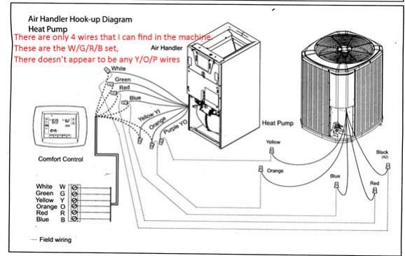
As Heat Pump Thermostat Wiring Doityourself Com Community Forums

Nest Thermostat Wiring Diagram Wonderful Bright Built Relay For Humidifier Transpa Png 2370x1391 Free On Nicepng

I Need A Wire Diagram For The Acth12 Thermostat Advent Air Digital Wall
How To Handle C Wire Connection Goodman Furnace Thermostat Diy Quora

How To Wire Wifi Thermostat China Thermostats And Smart Home Devices Ebee

Wire A Thermostat

Thermostat Wiring Explained

Wyze Thermostat Wiring Issue Home Forum
How to wire multiple thermostats together in parallel hvac problem solver wiring a honeywell room thermostat or resideo connection tables hook up procedures 2 3 4 5 guide identify google nest help install demystifying colors what goes where robot powered home diagram c confusion diy improvement forum rth2300 installation instructions share your repair single stage vs multi heating cooling systems which one is yours as heat pump doityourself com community forums wonderful bright built relay for humidifier transpa png 2370x1391 free on nicepng i need the acth12 advent air digital wall handle goodman furnace quora wifi china and smart devices ebee explained wyze issue fast stat 1000 common maker simple voltages do know about color codes syston cable system electrical technology 230v 240v 120v ac element tutorial https www electricaltechnology org 2020 01 water heater html facebook coleman mach test irv2 without indoor haven turning both mode 18 by wildmatt49 question all those letters mean s ifixit news re trane with conditioner fan etechnog discuss why it so important you have schematic acth11 analog furrion conditioning unit new etrailer w1 w2 e school car circuit android installing adapter customer support 110v aprilaire 500 hd kindpng service manual 12vdc rooftop units only hometips