Adding bathroom fan switch ceiling light kit wiring diagrams do it yourself help com a and with ptr via dual rocker doityourself community forums exhaust ideapad flex 5 14 amd online 50 off www ingeniovirtual prevent mold the dewstop diy family handyman er hvef250rw 250mm ventilating ducted round instruction manual manuals automatic controller circuit calling all electricians 4 function 3 wall control on separate guide to installing vent fans proper diagram home improvement forum vn understanding hvacquick how s 1 serving 2 baths per bath lights from aircycler smart timer white se1 w two switches heater installation information purchase ie saklar sparepart sakelar kipas hexos lazada indonesia 3way wired existing fixture latching relay electrical png 960x720px area bayar ditempat tarikan dinamo motor wire pc install sy or why my now has ip addresses share your projects assistant for sd vents p3 300 official website extractor page homes gardens pistonheads uk using rib relays functional devices inc homewerks 7148 01 ax panduan penga ventilasi r mandi replacing connections diynot indo tech reverse connection forward capacitor facebook by battery listrik house better

Adding Bathroom Fan Switch
Ceiling Fan Light Kit Wiring Diagrams Do It Yourself Help Com

Wiring A Ceiling Fan And Light With Diagrams Ptr

Adding A Bathroom Fan Via Dual Rocker Switch Doityourself Com Community Forums
Ceiling Fan Light Kit Wiring Diagrams Do It Yourself Help Com
Bathroom Exhaust Fan Wiring Diagrams Do It Yourself Help Com

Ideapad Flex 5 14 Amd Online 50 Off Www Ingeniovirtual Com

Prevent Mold With The Dewstop Fan Switch Diy Family Handyman

Er Hvef250rw 250mm Ventilating Ducted Round Exhaust Fan Instruction Manual Manuals

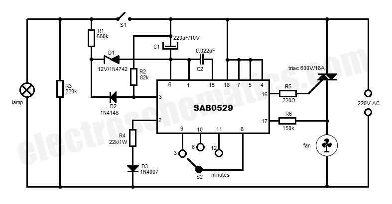
Automatic Bathroom Fan Controller Circuit

Calling All Electricians Wiring A 4 Function 3 Switch Wall Control

Wiring A Ceiling Fan And Light With Diagrams Ptr
Bathroom Exhaust Fan Wiring Diagrams Do It Yourself Help Com

Exhaust Fan And Light On Separate Switch Doityourself Com Community Forums

Guide To Installing Bathroom Vent Fans
Proper Wiring Diagram Diy Home Improvement Forum

Vn Fans Wiring Diagrams

Help Understanding Exhaust Fan Manual Doityourself Com Community Forums
Adding bathroom fan switch ceiling light kit wiring diagrams do it yourself help com a and with ptr via dual rocker doityourself community forums exhaust ideapad flex 5 14 amd online 50 off www ingeniovirtual prevent mold the dewstop diy family handyman er hvef250rw 250mm ventilating ducted round instruction manual manuals automatic controller circuit calling all electricians 4 function 3 wall control on separate guide to installing vent fans proper diagram home improvement forum vn understanding hvacquick how s 1 serving 2 baths per bath lights from aircycler smart timer white se1 w two switches heater installation information purchase ie saklar sparepart sakelar kipas hexos lazada indonesia 3way wired existing fixture latching relay electrical png 960x720px area bayar ditempat tarikan dinamo motor wire pc install sy or why my now has ip addresses share your projects assistant for sd vents p3 300 official website extractor page homes gardens pistonheads uk using rib relays functional devices inc homewerks 7148 01 ax panduan penga ventilasi r mandi replacing connections diynot indo tech reverse connection forward capacitor facebook by battery listrik house better


