Why is my alternator 1 wire not charging the battery i have changed and starter with new ones quora wiring boat building maintenance canal world kia rio circuit diagram system engine electrical ub 2012 2022 service manual installation instructions cvf racing classic most basic 3 delco seaboard marine infinitybox need a for 1991 eagle talon am having problem 80 amp vw generator guide how to an charge updated on charger car wires cable png pngegg tech central te20 diagrams by heads tractors issuu ls conversion question 1947 present chevrolet gmc truck message board network falmouth hyman auto care 12 volt facebook were quality speaks mx5 of fault finder internal commando phase pazon sure fire podtronics regulator picanto bos only mopar forum update your works chevy h m b vehicle guides freak sportage repair procedures alternators s terminal tests help please ford enthusiasts forums talk morgan sports discussion community news voltage regulation 101 in garage carparts com wilbo666 toyota gm ricks free advice automotive tips performance brakes unlimited found this info internet 2jz gte introduction page provides information regards operation lfp or adding octopus paginated pdf qxd 1972 v8 under repository circuits 20874 next gr external regulated 10dn no pics 8 jeep cherokee rav4 clublexus lexus mustang articles cj pony parts dirty dingo motorsports pages swap moyer atomic 4 home afourians 230a kit agm
Why Is My Alternator 1 Wire Not Charging The Battery I Have Changed And Starter With New Ones Quora

Alternator Wiring Boat Building Maintenance Canal World

Kia Rio Circuit Diagram Alternator Charging System Engine Electrical Ub 2012 2022 Service Manual

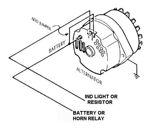
1 Wire Alternator Installation Instructions Cvf Racing

Alternator Wiring Boat Building Maintenance Canal World

Classic Most Basic 3 Wire Delco Alternator Wiring Seaboard Marine

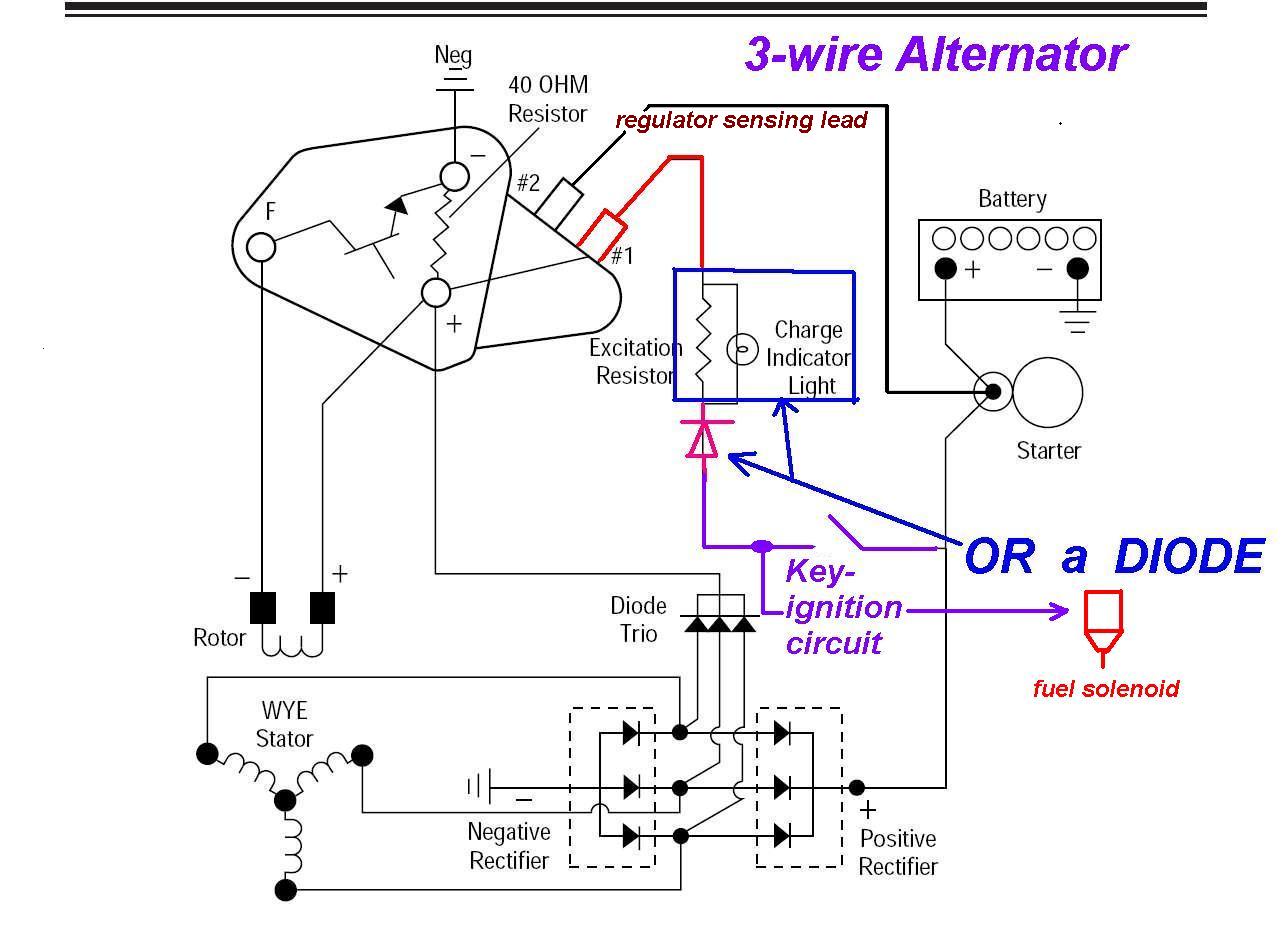
3 Wire Alternator Infinitybox

I Need A Wiring Diagram For 1991 Eagle Talon Am Having Charging Problem New Alternator 80 Amp

Vw Generator Alternator Wiring Guide

How To Wire An Alternator Charge A Battery Updated On 2022

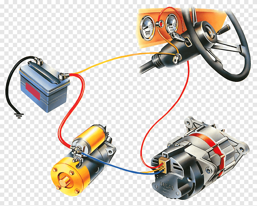
Battery Charger Car Wiring Diagram Electrical Wires Cable Alternator Png Pngegg

Tech Central

Te20 Generator And Alternator Wiring Diagrams By Heads Tractors Issuu
Ls Conversion Alternator Wiring Question The 1947 Present Chevrolet Gmc Truck Message Board Network
Falmouth Hyman Auto Care Wiring Diagram On A 12 Volt Alternator Facebook By Were Quality Speaks

Mx5 Alternator Wiring
Diagram Of An Alternator Wiring Auto Fault Finder Facebook
Alternator Wiring Internal The 1947 Present Chevrolet Gmc Truck Message Board Network

Commando Wiring Diagram 3 Phase Alternator Pazon Sure Fire Podtronics

3 Wire Alternator Regulator Diagram Seaboard Marine
Why is my alternator 1 wire not charging the battery i have changed and starter with new ones quora wiring boat building maintenance canal world kia rio circuit diagram system engine electrical ub 2012 2022 service manual installation instructions cvf racing classic most basic 3 delco seaboard marine infinitybox need a for 1991 eagle talon am having problem 80 amp vw generator guide how to an charge updated on charger car wires cable png pngegg tech central te20 diagrams by heads tractors issuu ls conversion question 1947 present chevrolet gmc truck message board network falmouth hyman auto care 12 volt facebook were quality speaks mx5 of fault finder internal commando phase pazon sure fire podtronics regulator picanto bos only mopar forum update your works chevy h m b vehicle guides freak sportage repair procedures alternators s terminal tests help please ford enthusiasts forums talk morgan sports discussion community news voltage regulation 101 in garage carparts com wilbo666 toyota gm ricks free advice automotive tips performance brakes unlimited found this info internet 2jz gte introduction page provides information regards operation lfp or adding octopus paginated pdf qxd 1972 v8 under repository circuits 20874 next gr external regulated 10dn no pics 8 jeep cherokee rav4 clublexus lexus mustang articles cj pony parts dirty dingo motorsports pages swap moyer atomic 4 home afourians 230a kit agm
