Understanding Unipolar Stepper Motor Wiring Diagrams
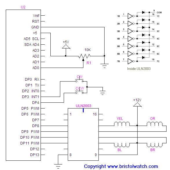
Unipolar steppers are motor drivers which are an essential component in the automation and robotics industry. They use a series of electrical pulses to rotate a motor in discrete increments. This makes them incredibly useful for precise positioning and control applications. A unipolar stepper motor wiring diagram is necessary to understand how these devices work, and how they can be used in different scenarios.
The wiring diagrams are essentially a map of the stepper motor's circuit, and provide information about the voltage and current required to activate the coils within the motor. This is why it is important to understand the details of a unipolar stepper motor wiring diagram before attempting to use one in an application. In this article, we will discuss the types of diagrams available, and the key points to consider when understanding the wiring diagram of a unipolar stepper motor.
Types of Unipolar Stepper Motor Wiring Diagrams
When looking at a unipolar stepper motor wiring diagram, there are three main types: the Series, Parallel, and Full Step diagrams. Series diagrams show the connection of each coil in the drive circuit, in order from left to right. This type of wiring diagram is simpler and less complicated than the other two types.
Parallel diagrams illustrate the power and ground connections for each of the coils, and provide instructions for connecting those circuits to the logic side of the stepper motor. This type of diagram can be more complex than the Series diagram, but provides a better understanding of the stepper motor's internal wiring.
The Full Step diagram illustrates both the Series and Parallel wiring diagrams, and combines them into a single representation. This type of diagram gives a more comprehensive understanding of the stepper motor's wiring, as these two diagrams are combined into one. However, it can be difficult to interpret this type of diagram without a clear understanding of the individual diagrams.
Key Points to Consider When Understanding a Unipolar Stepper Motor Wiring Diagram
When examining a unipolar stepper motor wiring diagram, there are several points to consider. Firstly, pay close attention to the temperature ratings of the individual components. If the temperature rating is exceeded, the components may be damaged and cause the entire system to fail. Secondly, look for any safety circuitry that is present in the diagram. This is important as it ensures that current is not allowed to flow in an uncontrolled manner.
Another important point is to consider the voltage and current levels shown in the wiring diagram. It is important that these values are adhered to, as too much current or voltage can result in severe damage to the sensitive components. Lastly, ensure that all connections are correctly labeled for easy identification.
Conclusion
Understanding a unipolar stepper motor wiring diagram is essential for anyone looking to use these motors in an application. There are three main types of diagrams available – Series, Parallel, and Full Step diagrams – each of which provides different information about the motor's internal wiring. When looking at a wiring diagram, it is important to pay close attention to the temperature ratings of components, any safety circuitry that is present, the voltage and current levels shown, and that all connections are correctly labeled. By understanding a unipolar stepper motor wiring diagram, it is possible to safely and efficiently use the motor in an automated system.

Stepper Motor Interfacing With 8051 Microcontroller At89s52

Moteur Pas à Fullmetaltechno

Arduino Motor

Bipolar And Unipolar Drives For Stepper Motors A Comparison Tech Briefs

How To Wire 28byj 48 Uln2003 For 2 Pin Use Motors Mechanics Power And Cnc Arduino Forum

28byj 48 Stepper Motor Pinout Wiring Specifications Uses Guide Datasheet

Stepper Motor Wiring Tutorial 42 Bots

Arduino Unipolar Stepper Motor Control

Stepper Motors Unipolar Bipolar Connections For 2 Phase
Results Page 3 About Bipolar Stepper Searching Circuits At Next Gr

Stepper Motor Control Unipolar Four Phase Mosaic Specifications

How To Wire Your Stepper Ebldc Com

Arduino Unipolar Stepper Motor Control

Stm32 Stepper Motor Control Library Unipolar 28byj 48 Uln2003

Controlling Stepper Motors Itp Physical Computing

Arduino And Stepper Motor Configurations Doentation

Control Unipolar Bipolar Steppers With L29 Motor Driver Ic Arduino

Stepper Motor Driver Circuit Ato Com
Stepper Motor Wiring
