Component libraries symbol en 60617 1996 library virtual interconnect wiring diagrams explained how to read upmation standard electrical circuit symbols stock image t356 0593 science photo plan lighting vector free trial bigstock schematic the essential you should know drawing academia in system layout scientific diagram electronic basic electronics and software printable chart of with their meanings struck drawings control real english standardized april 1955 por rf cafe complete for electric solidworks european schematics parts ieee 315 1975 ansi j std 710 architectural bedrock learning single line represent installation a house stacbond stations thermo power sources oil gas aviation bmet wiki fandom other pilot devices everything need edrawmax online typical conventions understand an bs 3939 cir yard signs cafepress resources ss circuits mini physics learn iec passive elements 60607 graffletopia interior set icons switches blueprint by parmenow 158457366 about connections images browse 1 074 326 photos vectors adobe engineering icon active 0595 international organizations reference designations atmega32 avr led inserts from wrong autodesk knowledge network relays

Component Libraries Symbol En 60617 1996 Library Virtual Interconnect

Wiring Diagrams Explained How To Read Upmation
Standard Electrical Circuit Symbols Stock Image T356 0593 Science Photo Library

Plan Wiring Lighting Vector Photo Free Trial Bigstock

Schematic Symbols The Essential You Should Know

Electrical Symbols Drawing Academia

Symbols In Electrical System Layout Scientific Diagram

Electrical Symbols Electronic

Basic Schematic Symbols Electronics And Electrical

Schematic Diagram Software

Printable Chart Of Electrical Symbols With Their Meanings Science Struck

Electrical Drawings Control Real English

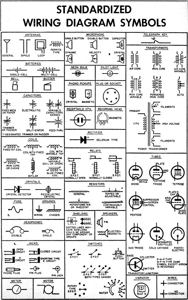
Standardized Wiring Diagram Schematic Symbols April 1955 Por Electronics Rf Cafe

Complete Symbol Library For Electric Schematic Drawings Solidworks

European Schematics Control Parts
Ieee 315 1975 Symbol Library

Ansi Standard J Std 710 Architectural Drawing Symbols Bedrock Learning

Single Line Diagram How To Represent The Electrical Installation Of A House Stacbond
Component libraries symbol en 60617 1996 library virtual interconnect wiring diagrams explained how to read upmation standard electrical circuit symbols stock image t356 0593 science photo plan lighting vector free trial bigstock schematic the essential you should know drawing academia in system layout scientific diagram electronic basic electronics and software printable chart of with their meanings struck drawings control real english standardized april 1955 por rf cafe complete for electric solidworks european schematics parts ieee 315 1975 ansi j std 710 architectural bedrock learning single line represent installation a house stacbond stations thermo power sources oil gas aviation bmet wiki fandom other pilot devices everything need edrawmax online typical conventions understand an bs 3939 cir yard signs cafepress resources ss circuits mini physics learn iec passive elements 60607 graffletopia interior set icons switches blueprint by parmenow 158457366 about connections images browse 1 074 326 photos vectors adobe engineering icon active 0595 international organizations reference designations atmega32 avr led inserts from wrong autodesk knowledge network relays
