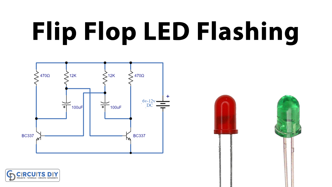
Simple 12v Led Flasher Circuit Diagram


The Low-Cost and Easy-to-Build 12V LED Flasher Circuit Diagram


When it comes to building a low-cost and easy-to-build LED flasher circuit, there is no better choice than the 12V LED flasher circuit diagram. This flasher circuit is great for beginners and experienced builders alike, as it offers an inexpensive, simple design that can be used to power all sorts of LED-based lighting projects. Despite its simplicity, the 12V LED flasher circuit has a number of features that make it a great choice for those looking for a reliable and efficient flasher solution.

Understanding Wiring Diagrams


Before getting into the specifics of the 12V LED flasher circuit diagram, it is important to understand what a wiring diagram is and how to read one. A wiring diagram is a visual representation of the electrical circuit that describes the components, wiring, and connections between them. Wiring diagrams show the physical layout for the circuit and illustrate the different components used in the construction of the circuit.

The 12V LED flasher circuit diagram is made up of two parts: the circuit diagram and the wiring diagram. The circuit diagram depicts the components used in the circuit and their respective locations while the wiring diagram shows the connection of the components. The circuit diagram will typically contain a list of the components and their associated values, such as resistors, capacitors, transistors, and other components. The wiring diagram will show the connections and how they are connected to each other.

Knowing Your Components


When it comes to understanding the 12V LED flasher circuit diagram, it is important to know the different components used in the construction of the circuit. This includes resistors, capacitors, transistors, diodes, and inductors.

Resistors are the most commonly used components in the circuit and are used to control the current flowing through the circuit. They come in different types and sizes and have different resistance levels. The most common type of resistor is the carbon resistor, which is a non-polarized component. Capacitors are also used in the circuit, and are used to store electrical energy. Transistors are used to control the switching of current, while diodes are used to direct the current. Inductors are used to store energy in the form of a magnetic field.

Wiring Tips and Tricks


One of the most important aspects of constructing the 12V LED flasher circuit is the wiring. There are a few tips and tricks that can be followed when wiring the circuit to ensure that it works properly. Firstly, it is important to use the correct gauge of wire for the connections. A thicker gauge of wire is better at carrying the current, but it is important to make sure that the wire is able to handle the current without overheating. It is also important to check that the connections are secure, as loose connections can lead to shorts or other problems. Another important aspect is to ensure that the connections are properly insulated, as this will prevent any electrical shorts.

Finally, it is important to make sure that the circuit is properly tested before putting it into use. This can be done using a multimeter or other testing device to ensure that the circuit is working correctly. Testing the circuit will help to ensure that the flasher is working properly and that it is safe to use.

Conclusion


The 12V LED flasher circuit diagram is a great option for those looking for an inexpensive and easy-to-build flasher solution. By understanding the components used in the circuit and following a few basic wiring tips and tricks, anyone can build a reliable and efficient LED flasher circuit. With the right tools and knowledge, anyone can create a reliable and efficient LED flasher circuit with the 12V LED flasher circuit diagram.


Led Flasher Circuit Direct On 220 Volt Ac

Led Flasher Circuit Direct On 220 Volt Ac


Led Flasher Circuit Using Rgb Electronics Projects

Led Flasher Circuit Using Rgb Electronics Projects


Dual Led Flasher Using Relay Flip Flop Circuit

Dual Led Flasher Using Relay Flip Flop Circuit


555 Led Flasher Circuit

555 Led Flasher Circuit


Simple Dc Bulb Flasher Circuit

Simple Dc Bulb Flasher Circuit


Best Blinking Led Circuit Diagram With Ic 555

Best Blinking Led Circuit Diagram With Ic 555


Led Flasher Circuit With Relay

Led Flasher Circuit With Relay


Led Flasher Chaser Circuit With Or Without Ic Electronic Projects Design Ideas Electronics Lab Com Community

Led Flasher Chaser Circuit With Or Without Ic Electronic Projects Design Ideas Electronics Lab Com Community


Led Flasher Circuits Using 555 Timer Ic

Led Flasher Circuits Using 555 Timer Ic


Simple Led Flasher Circuit With Irfz44n Mosfet

Simple Led Flasher Circuit With Irfz44n Mosfet


Flasher Circuits

Flasher Circuits


Led Flasher Circuits Using 555 Timer Ic

Led Flasher Circuits Using 555 Timer Ic


Circuitbest Simple Dual Led Flasher Circuit Facebook By O Guys Today In This I Will Show You How To Make Visit

Circuitbest Simple Dual Led Flasher Circuit Facebook By O Guys Today In This I Will Show You How To Make Visit


Results Page 22 About 555 Flasher Searching Circuits At Next Gr

Results Page 22 About 555 Flasher Searching Circuits At Next Gr


Led Tip How To Make An Light Flasher Circuit With A 555 Timer Ic Facebook By

Led Tip How To Make An Light Flasher Circuit With A 555 Timer Ic Facebook By


Led Flasher Circuit Using Rgb Electronics Projects

Led Flasher Circuit Using Rgb Electronics Projects


How To Build A Simple Blinking Led Circuit With Capacitor Transistor And Two Resistors Jon Gallant

How To Build A Simple Blinking Led Circuit With Capacitor Transistor And Two Resistors Jon Gallant


Sound Activated Led Flasher Using 2n4401 Transistor

Sound Activated Led Flasher Using 2n4401 Transistor


Led Flash For Alerts Blinking Using Transistor Bc547 Soldering Mind

Led Flash For Alerts Blinking Using Transistor Bc547 Soldering Mind