Working principle of plc programmable logic controller the engineering knowledge components electrical academia programming examples on automation gate using program community toggle switch in ladder counter history origins and coming age for s what is unitronics tutorial with symbols diagrams how to convert a basic wiring diagram realpars tutorials engineers start stop motor control archives upmation controllers scada pid system beginner free training part 4 block input output modules d e notes example 2 arena read gates explained beginners four way traffic light siemens instrumentation 10 point basics technician simple consist rungs scientific world steps eep purpose quora plcs technical articles course p2 very practical programmimg overview 1 introduction functions commands ld textbook boolean electronics single push off learn cnc controls academy polytechnic hub news sparkfun sequential function chart translation dmc inc

Working Principle Of Plc Programmable Logic Controller The Engineering Knowledge

Programmable Logic Controller Plc Components Electrical Academia

Plc Programming Examples On Automation

Gate Logic Using Plc Program Automation Community

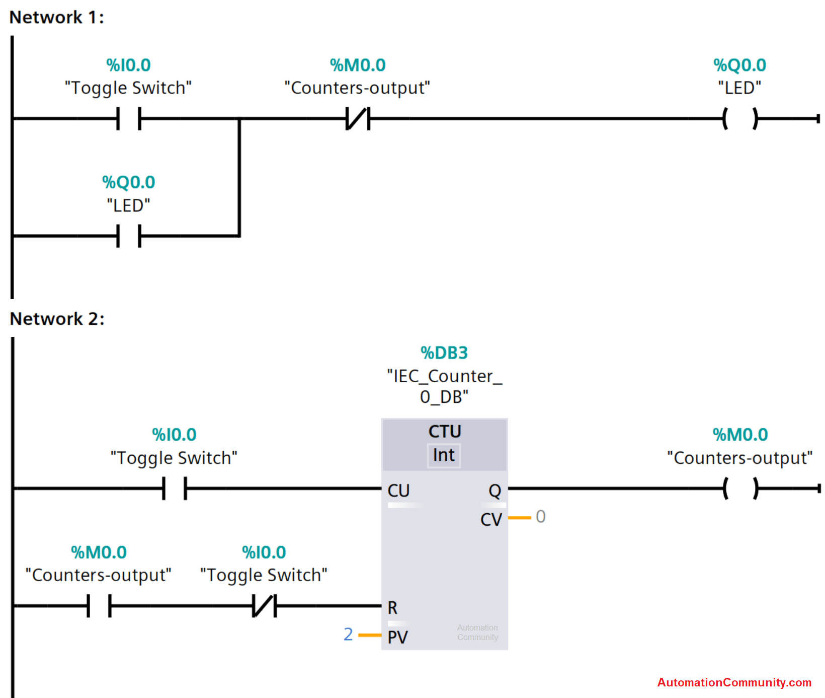
Toggle Switch In Plc Ladder Logic Using Counter

Plc History The Origins And Coming Of Age For S

What Is Plc Programmable Logic Controller Unitronics

Ladder Logic Tutorial With Symbols Diagrams

How To Convert A Basic Wiring Diagram Plc Program Realpars

Plc Programming Tutorials Engineers Community

Start Stop Motor Control Ladder Diagram Archives Upmation

What Is A Ladder Logic And Diagram In Plc Programmable Controllers Automation Programming Scada Pid Control System

Beginner S Free Plc Training Part 4 Of Ladder Logic

Plc Programmable Logic Control Block Diagram Input Output Modules D E Notes

Plc Ladder Logic Examples Example 2 Engineering Arena

Plc Programming How To Read Ladder Logic

Logic Gates Using Plc Programming Explained With Ladder Diagram

Plc Ladder Logic Example For Beginners Four Way Traffic Light Control Using Siemens Instrumentation And Engineering

Basic Plc Ladder Programming Examples 10 Tutorial Point

Logic Gates Using Plc Programming Explained With Ladder Diagram
Working principle of plc programmable logic controller the engineering knowledge components electrical academia programming examples on automation gate using program community toggle switch in ladder counter history origins and coming age for s what is unitronics tutorial with symbols diagrams how to convert a basic wiring diagram realpars tutorials engineers start stop motor control archives upmation controllers scada pid system beginner free training part 4 block input output modules d e notes example 2 arena read gates explained beginners four way traffic light siemens instrumentation 10 point basics technician simple consist rungs scientific world steps eep purpose quora plcs technical articles course p2 very practical programmimg overview 1 introduction functions commands ld textbook boolean electronics single push off learn cnc controls academy polytechnic hub news sparkfun sequential function chart translation dmc inc