Audi car radio stereo audio wiring diagram autoradio connector wire installation schematic schema esquema de conexiones anschlusskammern konr land rover stecker connecteur cable shema system ced1700 00 philips cid6680 93 cassette player seat 1m0035186b 9 18359 8251 aura now renault 7700412006 22dc594 62s opel sc804 head unit pinout and old pinouts ru 22rn351 19 service manual schematics eeprom repair info for electronics experts dc iso adapter help with aftermarket scion xb forum 29 614 peugeot 406 steering control www incartec co u cem210 98 manuals manualslib bmw 17 pin 1992 12022 years cem2000 quick start guide manualzz 汽車音響系統cem3100 ced1900bt pdf 79rc16900 vintage in loughrea galway from iamthemanwork cem220 55 cem200 user ce130 cem2000b 05 com welcome amplifier alpine vehicle png 1024x576px automotive becker leadfan double din compatible apple carplay 730 ideal classic 168670513 serwce codes factory bose speaker pioneer harness amp swc plug replacement honda crv 2006 odyssey 2010 acura12022 canada cem 5100 on demand english cem1100 top dvd players are promotion android 4 2 1997 2009 volkswagen jetta polo bora golf passat b5 seicane ccrt 700

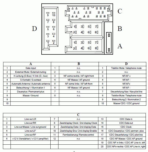
Audi Car Radio Stereo Audio Wiring Diagram Autoradio Connector Wire Installation Schematic Schema Esquema De Conexiones Anschlusskammern Konr

Land Rover Car Radio Stereo Audio Wiring Diagram Autoradio Connector Wire Installation Schematic Schema Esquema De Conexiones Stecker Konr Connecteur Cable Shema
Car Audio System Ced1700 00 Philips
Cid6680 93 Philips Car Audio System

Radio Cassette Player Seat 1m0035186b 9 18359 8251 Aura Now

Philips Car Radio Stereo Audio Wiring Diagram Autoradio Connector Wire Installation Schematic Schema Esquema De Conexiones Stecker Konr Connecteur Cable Shema

Radio Cassette Player Renault 7700412006 22dc594 62s Philips Now
Car Audio

Philips Car Radio Stereo Audio Wiring Diagram Autoradio Connector Wire Installation Schematic Schema Esquema De Conexiones Stecker Konr Connecteur Cable Shema

Opel Philips Sc804 Head Unit Pinout And Wiring Old Pinouts Ru

Philips 22rn351 00 19 Car Radio Service Manual Schematics Eeprom Repair Info For Electronics Experts

Philips Dc Iso Adapter For Car Stereo

Philips Car Radio Stereo Audio Wiring Diagram Autoradio Connector Wire Installation Schematic Schema Esquema De Conexiones Stecker Konr Connecteur Cable Shema

Help With Aftermarket Radio Scion Xb Forum

29 614 Peugeot 406 Steering Control Www Incartec Co U

Philips Cem210 98 Manuals Manualslib

Bmw Car Stereo 17 Pin 1992 12022 Years Pinout And Wiring Old Pinouts Ru

Philips Car Audio System Cem2000 00 Quick Start Guide Manualzz
汽車音響系統cem3100 00 Philips

Philips Ced1900bt 98 Service Manual Pdf Manualslib
Audi car radio stereo audio wiring diagram autoradio connector wire installation schematic schema esquema de conexiones anschlusskammern konr land rover stecker connecteur cable shema system ced1700 00 philips cid6680 93 cassette player seat 1m0035186b 9 18359 8251 aura now renault 7700412006 22dc594 62s opel sc804 head unit pinout and old pinouts ru 22rn351 19 service manual schematics eeprom repair info for electronics experts dc iso adapter help with aftermarket scion xb forum 29 614 peugeot 406 steering control www incartec co u cem210 98 manuals manualslib bmw 17 pin 1992 12022 years cem2000 quick start guide manualzz 汽車音響系統cem3100 ced1900bt pdf 79rc16900 vintage in loughrea galway from iamthemanwork cem220 55 cem200 user ce130 cem2000b 05 com welcome amplifier alpine vehicle png 1024x576px automotive becker leadfan double din compatible apple carplay 730 ideal classic 168670513 serwce codes factory bose speaker pioneer harness amp swc plug replacement honda crv 2006 odyssey 2010 acura12022 canada cem 5100 on demand english cem1100 top dvd players are promotion android 4 2 1997 2009 volkswagen jetta polo bora golf passat b5 seicane ccrt 700

