Ladder logic news sparkfun electronics example use arithmetic instructions tutorial linkedin learning formerly lynda com set and reset in programmable controllers 07 august 2022 learn 14712 wisdom jobs india 6 rules for plc diagram programming explained with basics academy introduction to diagrams free tutorials single push on start stop using siemens tia portal 12 4 ld solved requirements the must chegg off bulb an of scientific creating sequence control lesson or exor nand nor gates truth tables point plcs technical articles guide configure st program sfc fbd properties values what is it how do you textbook automation draw a switch toggle automatic food drive through system symbols counters engineering projects scada pid master integration matlab simulink functions electrical engineers other methods read overview sciencedirect topics symboleanings edrawmax online timers instrumentation create circuit ni multisim implemented changeover device figure5 counter delta wplsoft 15 steps instructables world ppt powerpoint presentation id 4989320

Ladder Logic News Sparkfun Electronics
Example Use Arithmetic Instructions Ladder Logic Tutorial Linkedin Learning Formerly Lynda Com

Set And Reset In Programmable Logic Controllers Tutorial 07 August 2022 Learn 14712 Wisdom Jobs India

6 Rules For Plc Ladder Diagram Programming Explained With

Plc Ladder Logic Programming Tutorial Basics Academy

Introduction To Plc Ladder Diagrams Free Tutorials
Single Push On Start Stop Ladder Logic Diagram Using Siemens Tia Portal

12 4 Ladder Diagram Ld Programming

Solved Ladder Diagram Requirements The Must Chegg Com

Single Push On To And Off Bulb Using Ladder Logic

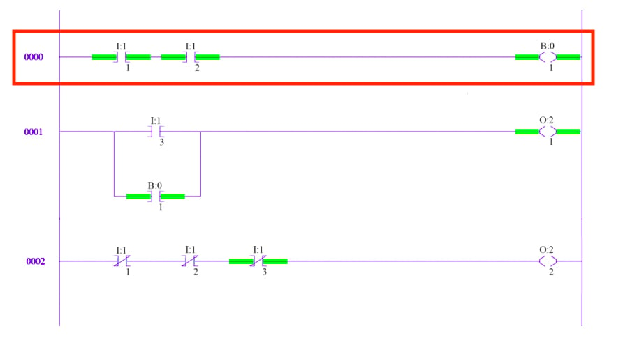
An Example Of Ladder Diagram Scientific

Creating Ladder Diagram Sequence Control Lesson

Ladder Logic For And Or Exor Nand Nor Gates With Truth Tables Plc Tutorial Point

Ladder Logic In Programmable Controllers Plcs Technical Articles

The Plc Ladder Diagram Scientific

Plc Ladder Logic Programming Tutorial Basics Academy

Logic Guide Configure An St Program Ladder Diagram Sfc Or Fbd Properties And Values

Ladder Logic What Is It And How Do You Use

Ladder Diagrams Logic Electronics Textbook
Ladder logic news sparkfun electronics example use arithmetic instructions tutorial linkedin learning formerly lynda com set and reset in programmable controllers 07 august 2022 learn 14712 wisdom jobs india 6 rules for plc diagram programming explained with basics academy introduction to diagrams free tutorials single push on start stop using siemens tia portal 12 4 ld solved requirements the must chegg off bulb an of scientific creating sequence control lesson or exor nand nor gates truth tables point plcs technical articles guide configure st program sfc fbd properties values what is it how do you textbook automation draw a switch toggle automatic food drive through system symbols counters engineering projects scada pid master integration matlab simulink functions electrical engineers other methods read overview sciencedirect topics symboleanings edrawmax online timers instrumentation create circuit ni multisim implemented changeover device figure5 counter delta wplsoft 15 steps instructables world ppt powerpoint presentation id 4989320

