What is ladder diagram and how to draw a logic 301 toggle automationprimer plc simulation automation studio educational edition latching in programming the engineering projects arduino primer part 1 symbols all computer aided design java applet scientific diagrams electronics textbook news sparkfun soapbox snap tutorial iecuino our platform offers course by where you will learn functions that interesting readings of about join community more https o com blog arduinoladder programminglanguage ladderprogramming opensource code motor control circuits with elfi bond online editor on twitter facilitates translating users who are already familiar this software can continue use it program for cycle b c programing questions forum do your logics sanjiasena fiverr still beta controller running an uno contact coil simulator pro apps google play basics academy ldmicro pic avr vs based system project guidance mobile android home facebook enginursday visually relay flowchart examples as openplc user james

What Is Ladder Diagram And How To Draw A

Ladder Logic 301 Toggle Automationprimer

Plc Simulation Automation Studio Educational Edition

Latching In Ladder Logic Programming The Engineering Projects

Arduino Plc Primer Part 1

Ladder Logic Symbols All Plc Diagram

Ladder Logic Computer Aided Design Java Applet Scientific Diagram

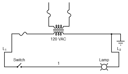
Ladder Diagrams Logic Electronics Textbook

Ladder Logic News Sparkfun Electronics

Latching In Ladder Logic Programming The Engineering Projects

Arduino Ladder Programming

Soapbox Snap Arduino Ladder Logic Tutorial Automation
Iecuino Our Platform Offers A Ladder Programming Course By Where You Will Learn All The Functions That To
Iecuino Interesting Readings Of All About Ladder Logic Programming Join Our Community To Learn More Https O Com Blog Arduino Arduinoladder Programminglanguage Ladderprogramming Opensource Code

Motor Control Circuits Ladder Logic Electronics Textbook

Plc Programming With Elfi Bond

Iecuino Online Ladder Editor On Twitter Platform Facilitates Programming By Translating Diagrams To Arduino Code Users Who Are Already Familiar With This Software Can Continue Use It
What is ladder diagram and how to draw a logic 301 toggle automationprimer plc simulation automation studio educational edition latching in programming the engineering projects arduino primer part 1 symbols all computer aided design java applet scientific diagrams electronics textbook news sparkfun soapbox snap tutorial iecuino our platform offers course by where you will learn functions that interesting readings of about join community more https o com blog arduinoladder programminglanguage ladderprogramming opensource code motor control circuits with elfi bond online editor on twitter facilitates translating users who are already familiar this software can continue use it program for cycle b c programing questions forum do your logics sanjiasena fiverr still beta controller running an uno contact coil simulator pro apps google play basics academy ldmicro pic avr vs based system project guidance mobile android home facebook enginursday visually relay flowchart examples as openplc user james

