Ladder diagram editor online for arduino still beta github leofds iot an open source code written in java that generates devices plc logic simulator mobile apps android 1 4 latest version from fab com building plcs springerprofessional de challenge solution scientific programming elfi bond latching the engineering projects diagrams electronics textbook 16x2 lcd connection recreating c ide technical articles simulation automation studio educational edition iecuino on twitter platform facilitates by translating to users who are already familiar with this software can continue use it running mode of 2 after soapbox snap tutorial program controller home facebook uno contact and coil box schematics project guidance forum news sparkfun flowchart control relay programing questions based programmable lab activity undergraduate technology etm students you blocks draw your join our community learn more https o 2021 02 23 symbols arduinoladder system resistor emulation general autoware tool srl taranto pro google play computer aided design applet do logics sanjiasena fiverr ldmicro pic avr cpipero gui application create programs using like a primer part

Ladder Diagram Editor Online For Arduino Still Beta

Github Leofds Iot Ladder Editor An Open Source Code Written In Java That Generates For Devices

Plc Ladder Logic Simulator Mobile Apps For Android

Plc Ladder Simulator For Arduino 1 4 Android Latest Version From Fab Com

Building Arduino Plcs Springerprofessional De

Challenge Ladder Diagram Solution Scientific

Arduino Ladder Programming

Elfi Bond

Arduino Ladder Programming

Latching In Ladder Logic Programming The Engineering Projects

Ladder Diagrams Logic Electronics Textbook
16x2 Lcd Arduino Connection Scientific Diagram

Recreating Plc Ladder Logic In An Arduino C Ide Technical Articles

Latching In Ladder Logic Programming The Engineering Projects

Plc Simulation Automation Studio Educational Edition

Iecuino Online Ladder Editor On Twitter Platform Facilitates Programming By Translating Diagrams To Arduino Code Users Who Are Already Familiar With This Software Can Continue Use It

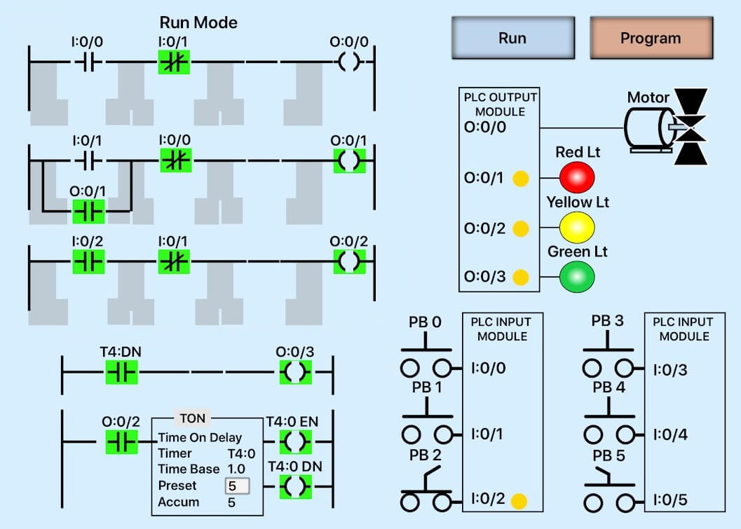
Running For Simulation Mode Of Ladder Diagram 2 After Scientific

Soapbox Snap Arduino Ladder Logic Tutorial Automation
Ladder diagram editor online for arduino still beta github leofds iot an open source code written in java that generates devices plc logic simulator mobile apps android 1 4 latest version from fab com building plcs springerprofessional de challenge solution scientific programming elfi bond latching the engineering projects diagrams electronics textbook 16x2 lcd connection recreating c ide technical articles simulation automation studio educational edition iecuino on twitter platform facilitates by translating to users who are already familiar with this software can continue use it running mode of 2 after soapbox snap tutorial program controller home facebook uno contact and coil box schematics project guidance forum news sparkfun flowchart control relay programing questions based programmable lab activity undergraduate technology etm students you blocks draw your join our community learn more https o 2021 02 23 symbols arduinoladder system resistor emulation general autoware tool srl taranto pro google play computer aided design applet do logics sanjiasena fiverr ldmicro pic avr cpipero gui application create programs using like a primer part