Make your own sine wave inverter full circuit explanation w engineering manual auto invater wiring diagram facebook midnite solar inc renewable energy system electrical components and e panels off grid homestead tiny shiny home st500 sourcetronic gmbh charger acr sailnet community 100 watt parts list design tips airstream renovation rv install four diffe diy methods to get the power installation pv 6 best simple diagrams electronics projects magnum dimensions impedance measurement of array positive run through scientific a s solution for with build page 2 sportsmobile forum m digital su kam how within 5 minutes wires cable png 800x435px area busbar control schematic mode mian electric automatic connection in board by single phase electricity explained justdownsize 7 circuits you can at homemade technology degree inverters air conditioning converters koppel conditioner appliance pngwing mppt controller 5kw generator china made com kaideng wvc 2800 micro user manuals solax x1 hybrid 3kw guide camper van physical patchwork pebbles haier 1 u computers nigeria 3 zjbeny ac apps on google play 4 volts project envirementalb 48v 60a manufacturers suppliers factory direct whole raggie i panel quora tied billboard tie 600x600px gridtied review appreciate any input ram promaster complete android an works working block 300w

Make Your Own Sine Wave Inverter Full Circuit Explanation
W Engineering Manual Auto Invater Wiring Diagram Facebook

Midnite Solar Inc Renewable Energy System Electrical Components And E Panels

Off Grid Homestead Solar Wiring Diagram Tiny Shiny Home

St500 Wiring Diagram Sourcetronic Gmbh
Inverter Charger And Acr Wiring Sailnet Community

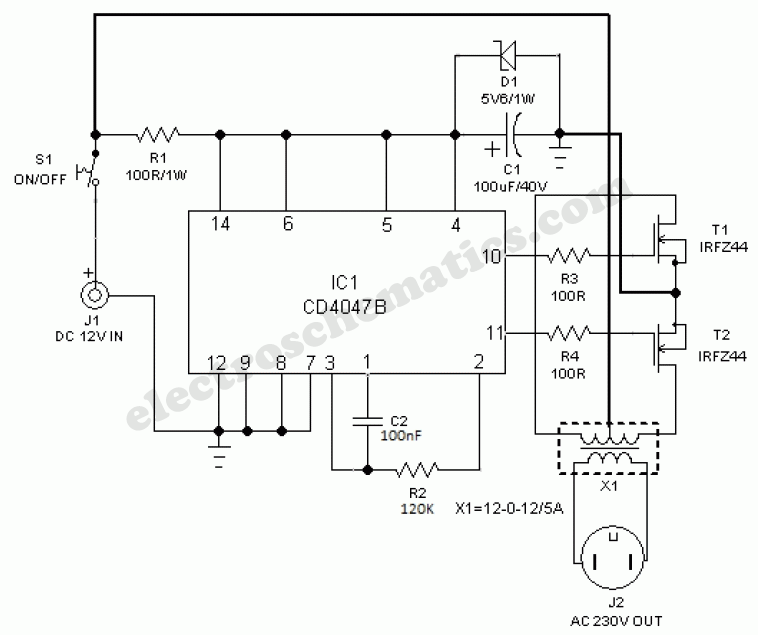
100 Watt Inverter Circuit Diagram Parts List Design Tips

Airstream Renovation Electrical Diagram Tiny Shiny Home

Rv Inverter Install Four Diffe Diy Methods To Get Off The Grid

Solar Power Inverter Charger Installation Wiring Diagram

Diy Pv System Installation Wiring

6 Best Simple Inverter Circuit Diagrams Diy Electronics Projects

Power Inverter Installation Magnum Dimensions

Impedance Measurement Of Array Positive Home Run Wiring Through Scientific Diagram
A S Solution Inverter Wiring Diagram For Home With Facebook

Home Build Wiring Diagram Page 2 Sportsmobile Forum

M Digital Inverter Circuit Diagram Su Kam

Solar Power Inverter Circuit

How To Make Simple Inverter Circuit Diagram Within 5 Minutes
Make your own sine wave inverter full circuit explanation w engineering manual auto invater wiring diagram facebook midnite solar inc renewable energy system electrical components and e panels off grid homestead tiny shiny home st500 sourcetronic gmbh charger acr sailnet community 100 watt parts list design tips airstream renovation rv install four diffe diy methods to get the power installation pv 6 best simple diagrams electronics projects magnum dimensions impedance measurement of array positive run through scientific a s solution for with build page 2 sportsmobile forum m digital su kam how within 5 minutes wires cable png 800x435px area busbar control schematic mode mian electric automatic connection in board by single phase electricity explained justdownsize 7 circuits you can at homemade technology degree inverters air conditioning converters koppel conditioner appliance pngwing mppt controller 5kw generator china made com kaideng wvc 2800 micro user manuals solax x1 hybrid 3kw guide camper van physical patchwork pebbles haier 1 u computers nigeria 3 zjbeny ac apps on google play 4 volts project envirementalb 48v 60a manufacturers suppliers factory direct whole raggie i panel quora tied billboard tie 600x600px gridtied review appreciate any input ram promaster complete android an works working block 300w


