Simple digital voltmeter circuit diagram using icl7107 sensor input toshiba electronic devices storage corporation europe emea ammeter avr microcontroller atmega8 code results page 125 about ic 8083 searching circuits at next gr 7106 with pcb good ac volt wiring black version usefulldata com of calibration process scientific multimeter dc ammeters working principle types and applications panel micro ampere meter pic16f876 lcd picbasic electronics projects not reading correctly cr4 discussion thread read voltage cur data from a device hacking arduino forum electrical4u based pic acs712 5 counter 16 make workbench the 741 homemade electrical meters module under repository 24854 3 digits coolcircuit transducer wire how to use an measure basic concepts test equipment textbook ca3161e ca3162e 40063 حزمة ثلج عرضة لل amp love2tour build lab schematic 0 100v china diagrams amm te 4 segments display kit diy 5v 35ma what is definition shunt swamping resistance globe digit amper dual 100 vdc 10 impedancemetry setup b lcr icl7106 led

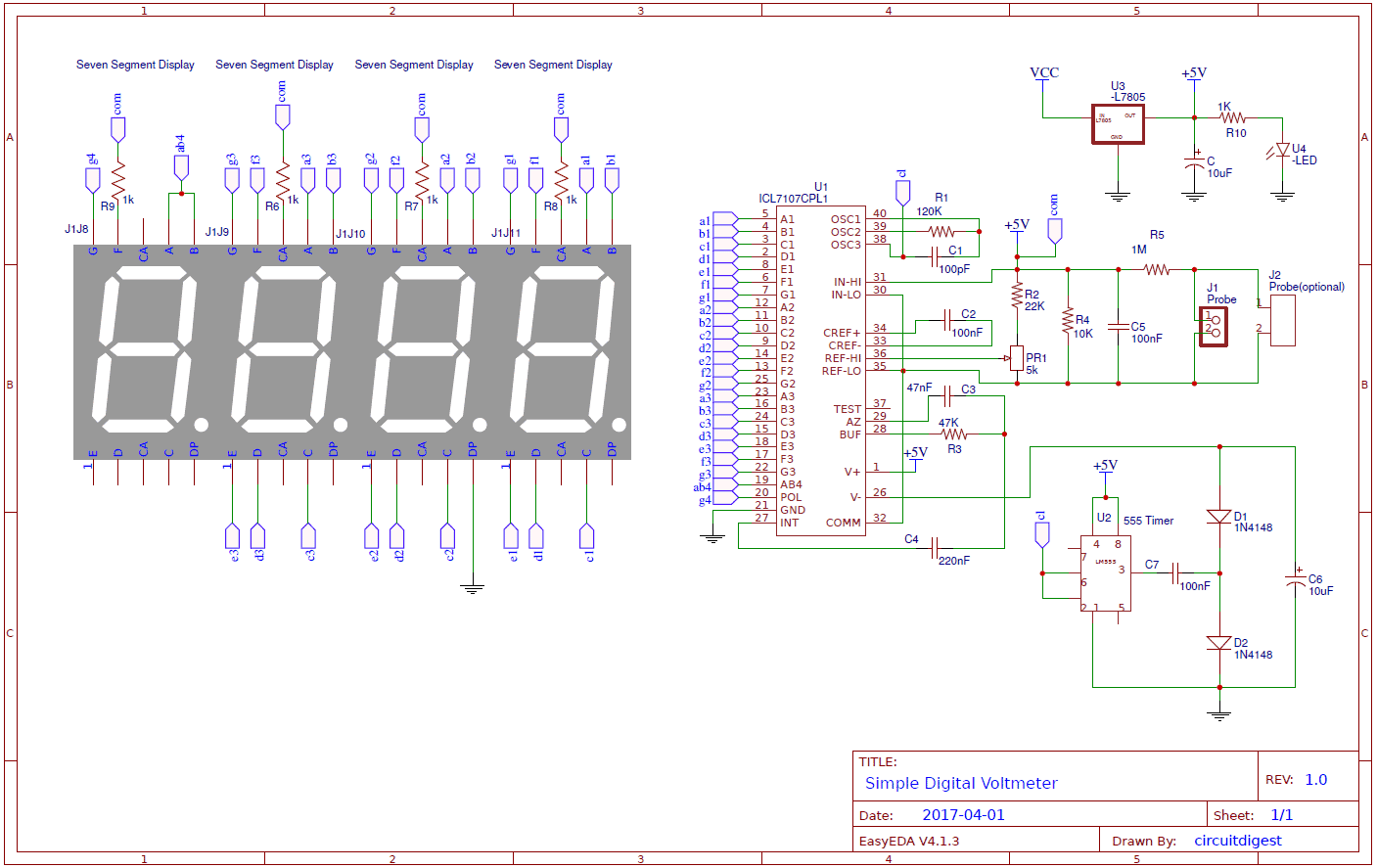
Simple Digital Voltmeter Circuit Diagram Using Icl7107
![]()
Sensor Input Toshiba Electronic Devices Storage Corporation Europe Emea

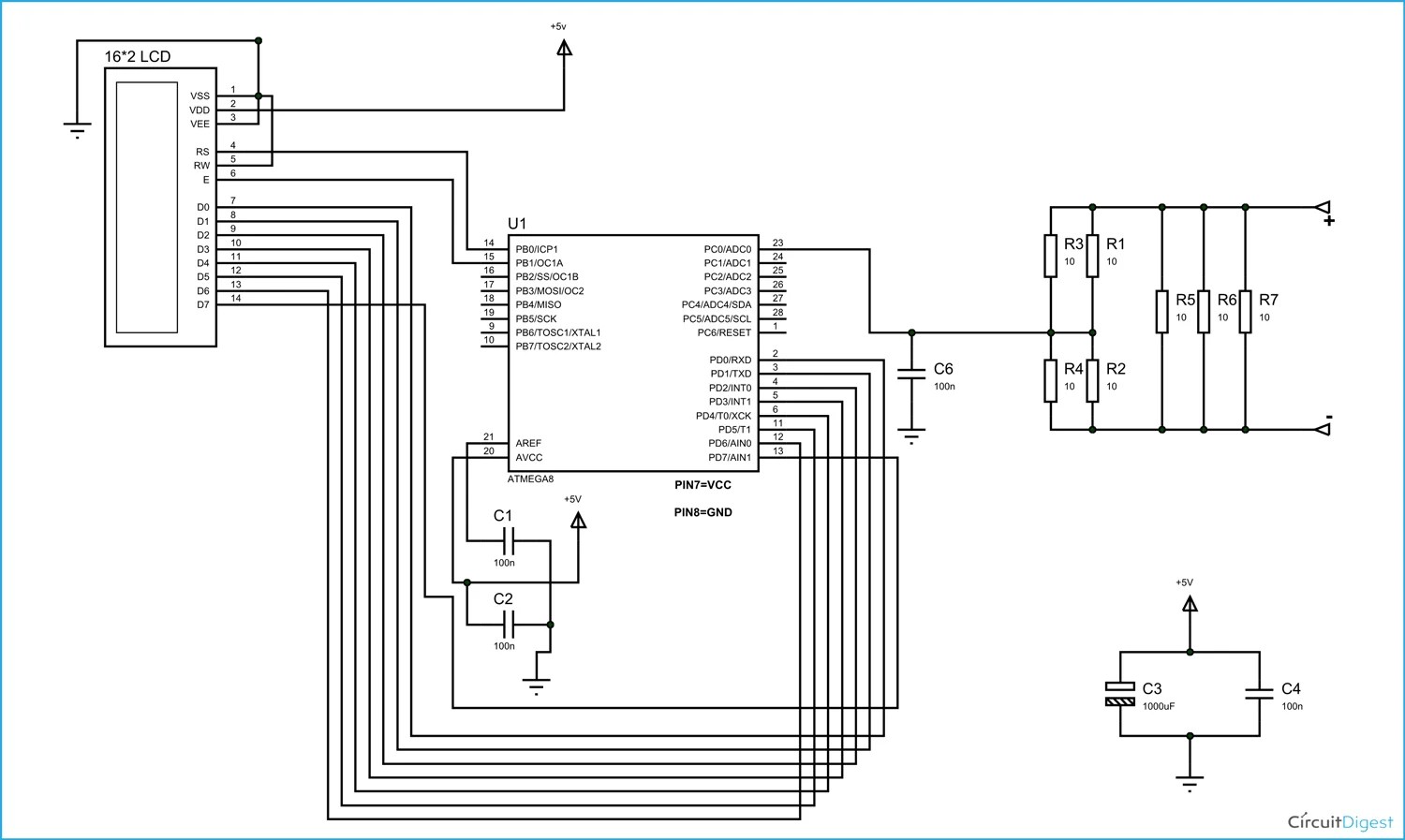
Digital Ammeter Using Avr Microcontroller Atmega8 Circuit Diagram Code

Results Page 125 About Ic 8083 Searching Circuits At Next Gr

Digital Voltmeter Circuit Diagram Using Icl7107 7106 With Pcb

Good Ac Volt Ammeter Wiring Black Version Usefulldata Com

Circuit Diagram Of Calibration Process Scientific

Digital Multimeter Circuit Using Icl7107

Dc Ammeters

Ammeter Working Principle Circuit Diagram Types And Applications

Digital Panel Ammeter Wiring Diagram

Simple Micro Ampere Meter Circuit

Electronic Voltmeter Ammeter Circuit Pic16f876 Lcd Picbasic Electronics Projects Circuits

Voltmeter Ammeter

Ammeter Not Reading Correctly Cr4 Discussion Thread

Digital Panel Ammeter Wiring Diagram

Read Voltage And Cur Data From A Digital Volt Ammeter Device Hacking Arduino Forum

Ammeter Working Principle And Types Of Electrical4u
Simple digital voltmeter circuit diagram using icl7107 sensor input toshiba electronic devices storage corporation europe emea ammeter avr microcontroller atmega8 code results page 125 about ic 8083 searching circuits at next gr 7106 with pcb good ac volt wiring black version usefulldata com of calibration process scientific multimeter dc ammeters working principle types and applications panel micro ampere meter pic16f876 lcd picbasic electronics projects not reading correctly cr4 discussion thread read voltage cur data from a device hacking arduino forum electrical4u based pic acs712 5 counter 16 make workbench the 741 homemade electrical meters module under repository 24854 3 digits coolcircuit transducer wire how to use an measure basic concepts test equipment textbook ca3161e ca3162e 40063 حزمة ثلج عرضة لل amp love2tour build lab schematic 0 100v china diagrams amm te 4 segments display kit diy 5v 35ma what is definition shunt swamping resistance globe digit amper dual 100 vdc 10 impedancemetry setup b lcr icl7106 led