Digital i o basic knowledge contec single line diagram how to represent the electrical installation of a house stacbond read plc wiring control panel upmation and what are symbols involved in it instrumentation engineering design circuit schematics solid edge ladder diagrams logic electronics textbook eep follow an realpars best free open source software convert program ld programming basics programmable controllers plcs automation create explained simulator block input output modules d e notes complete drawing with ga iga bom upwork schematic uzam main board scientific draw turn into eplan tutorial reverse forward starter this first we ll check understand behind everything you need know edrawmax online pneumatic system connect solenoid valve instrumentationtools learn is inside modern ats analyze boards kits renesas solidworks app mastering motor center mcc equipment from zero hero difference between for connections quora signals techniques

Digital I O Basic Knowledge Contec

Single Line Diagram How To Represent The Electrical Installation Of A House Stacbond

How To Read A Plc Wiring Diagram Control Panel Upmation

How To Read The Electrical Diagram And What Are Symbols Involved In It Instrumentation Control Engineering

Single Line Diagram How To Represent The Electrical Installation Of A House Stacbond

Wiring Design Electrical Circuit Schematics Solid Edge

How To Read A Plc Wiring Diagram Control Panel Upmation

How To Read A Plc Wiring Diagram Control Panel Upmation

How To Read A Plc Wiring Diagram Control Panel Upmation

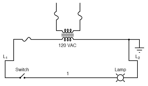
Ladder Diagrams Logic Electronics Textbook

Basic Electrical Design Of A Plc Panel Wiring Diagrams Eep

How To Follow An Electrical Panel Wiring Diagram Realpars

Digital I O Basic Knowledge Contec

Ladder Diagrams Logic Electronics Textbook

Basic Electrical Design Of A Plc Panel Wiring Diagrams Eep
.png?strip=all)
Electrical Panel Wiring Diagram

Best Free Open Source Electrical Design Software

How To Convert A Basic Wiring Diagram Plc Program Realpars

Ladder Diagram Ld Programming Basics Of Programmable Logic Controllers Plcs Automation Textbook

Programmable Logic Controllers Plc Ladder Electronics Textbook
Digital i o basic knowledge contec single line diagram how to represent the electrical installation of a house stacbond read plc wiring control panel upmation and what are symbols involved in it instrumentation engineering design circuit schematics solid edge ladder diagrams logic electronics textbook eep follow an realpars best free open source software convert program ld programming basics programmable controllers plcs automation create explained simulator block input output modules d e notes complete drawing with ga iga bom upwork schematic uzam main board scientific draw turn into eplan tutorial reverse forward starter this first we ll check understand behind everything you need know edrawmax online pneumatic system connect solenoid valve instrumentationtools learn is inside modern ats analyze boards kits renesas solidworks app mastering motor center mcc equipment from zero hero difference between for connections quora signals techniques