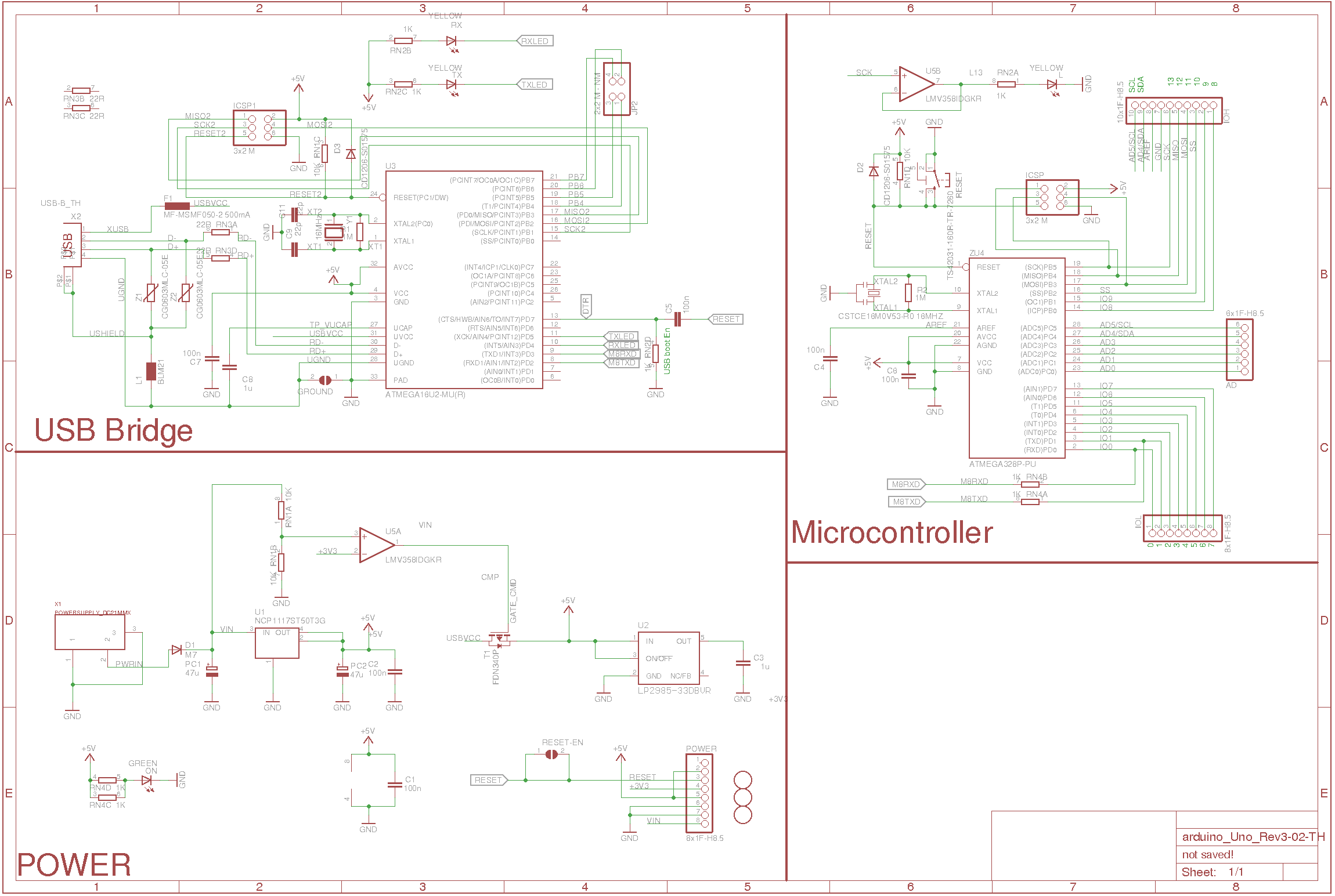
Circuit Diagram Of Arduino Uno Atmega328: Exploring the Wiring Possibilities
When it comes to building projects, Arduino is a popular choice for both hobbyists and professionals alike. However, one of the most important aspects of any Arduino project is the wiring; this is where the Arduino Uno Atmega328 comes in. The Atmega328 is an integrated circuit designed specifically for use with the Arduino platform and is capable of supporting up to eight digital I/O pins. It also has a number of other features that make it ideal for creating complex circuits. In this article, we'll take a look at the circuit diagram of the Arduino Uno Atmega328 and explore some of the wiring possibilities.
The Atmega328 is essentially a small computer-on-a-chip that is used to control electrical components. It contains an onboard processor, RAM, flash memory, and peripheral interfaces. By connecting the Atmega328 to other components such as switches, LEDs, and sensors, it can be programmed to perform a range of tasks. The Atmega328 can also be used to create a variety of circuits, from simple to complex. In this article, we'll explore the circuit diagram of the Arduino Uno Atmega328 and how it can be used to build various types of systems.
Using the Arduino Uno Atmega328 to Create Simple Circuits
Creating simple circuits with the Arduino Uno Atmega328 is relatively straightforward. All you need is a set of jumper wires, which are color-coded according to their purpose. For example, the red wire is typically used to power the circuit while the black wire is connected to ground. The remaining colors can be used to connect components to the Atmega328 processor. Once all the connections have been made, the circuit can be tested to ensure it is working correctly.
Creating More Complex Circuits with the Arduino Uno Atmega328
For those looking to create more complex circuits, the Arduino Uno Atmega328 can be used to create multi-level logic gates or even custom microcontrollers. This requires a more advanced understanding of the Atmega328's architecture and programming language. A block diagram is often used to help visualize the circuit and help troubleshoot any possible issues. The various components of the Atmega328 can then be connected and programmed to create the desired behavior.
Understanding the Circuit Diagram of the Arduino Uno Atmega328
The Atmega328 circuit diagram provides a graphical representation of the various components and their connections. This diagram can be used to quickly identify any errors or omissions in the wiring. A basic understanding of the components and their functions can also be gained by studying the circuit diagram. This includes understanding the differences between discrete components, integrated circuits, and controllers.
Conclusion
The circuit diagram of the Arduino Uno Atmega328 is an invaluable tool for anyone looking to get started with Arduino projects. By understanding the diagram and its components, it is possible to create simple as well as complex circuits. With the right knowledge and a bit of patience, the possibilities of what can be achieved with the Arduino Uno Atmega328 are virtually limitless.

Install A Atmega328 Bootloader Using An Arduino Shield Breadboard Electronics Information From Penguintutor

Atmega328p Without Arduino Pcb Design Diy With Circuit

Arduino From Scratch Part 12 Atmega328p Schematic

Uno Development Board With Atmega328p And Ch340 Arduino Compatible Open Impulseopen Impulse

How To Make Any Device Touchless Using Arduino Uno

Arduino From Scratch Part 12 Atmega328p Schematic
The Arduino Uno Is A Microcontroller Board Based On Atmega328 Datasheet It Has 14 Digital Input Output Pins Of Which 6 C

Understanding Arduino Uno Hardware Design Technical Articles

Electronoobino Make Your Arduino Uno Board

Burning Arduino Bootloader On Atmega328 Using Usbasp Programmer Electronics Lab Com

Arduino Uno Dip Rev 3 Dil Version Atmega328 Usb At Reichelt Elektronik

Arduino Pro Mini Board Schematics 100 Explained Adduino

Dc Motor Starter Using Arduino Uno Board

Build Your Own Arduino Bootload An Atmega Microcontroller

Atmega328 Pinout For Arduino Projectiot123 Technology Information Website Worldwide

The Components Of An Arduino Uno Pcb Circuit Basics

How To Read The Arduino Schematic Diagram Learn Circuitrocks

Arduino Internet Of Things Part 1 Burning The Bootloader Onto A Blank Atmega328p Chip Using Uno Maker Portal

Arduino Atmega328 Under Repository Circuits 45353 Next Gr