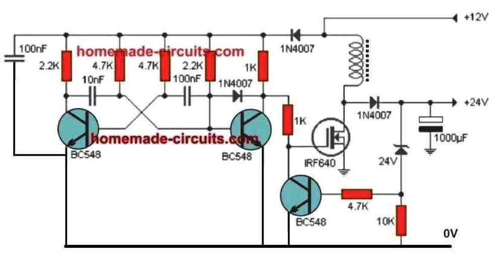
Car Charger Circuit Diagram


Understanding Car Charger Circuit Diagrams and Wiring


When it comes to understanding the intricacies of car wiring, the car charger circuit diagram is an invaluable tool. Not only does it provide a useful visual representation of the wiring, but it also provides important safety information to help you avoid hazards. In this article, we will delve into the basics of wiring diagrams and how they can be used to make your life easier.

The car charger circuit diagram is a diagram that shows the various electrical components and their connections in a car's wiring system. This diagram is very useful when attempting to troubleshoot any electrical issue with your car. It will help you understand the different components and their purpose. The diagram can be divided into several sections, each highlighting a different aspect of the wiring system. Let's take a closer look at how these sections can be used to make your job easier.

Reading Car Charger Circuit Diagrams


When reading a car charger circuit diagram it is important to familiarize yourself with the symbols used. Most diagrams will have common symbols such as resistors, capacitors, diodes, transistors, and switches. Make sure to take note of which symbol is used for each component. With this knowledge, you will be able to determine what type of device it is and how it fits into the wiring system.

Once you are familiar with the symbols, you can then begin to understand the circuit diagram. Each section of the diagram will provide information about the components and how they connect to each other. You should be able to identify the power switch, the power supply, the starter motor, and the ground connection. With this information, you can start to map out the entire wiring system.

Gaining Insight from Car Charger Circuit Diagrams


In addition to providing you with a visual representation of the wiring system, the car charger circuit diagram can also provide you with insight into the wiring system's performance. By looking at the voltage levels of each component, you can gain useful information regarding the efficiency of the wiring system. This information can be used to adjust the wiring system to improve its performance.

A car charger circuit diagram can also provide you with insight into the current running through the system. This can be extremely useful when troubleshooting problems in the wiring system. If there is a higher current running through certain parts of the wiring system, it may indicate the presence of a short circuit or another issue. By examining the voltage levels in the diagram, you can determine which components could be causing the problem.

Common Issues with Car Chargers Circuit Diagrams


While car charger circuit diagrams are incredibly useful, they can also cause some issues if not properly understood. One of the most common issues is incorrect wiring. If the diagram is not understood, it is possible to wire the components incorrectly which could lead to serious damage or even an electrical fire.

Another potential issue is overloading the wiring system. If too many components are connected to the same circuit, the wiring system may be overloaded and the components may not get the proper amount of power. This can lead to problems such as short circuiting and even a fire in extreme cases. Be sure to check the current ratings of each component before connecting it to the circuit.

Conclusion


Car charger circuit diagrams are an invaluable tool for anyone working on a vehicle's wiring system. They provide an easy way to understand the wiring system and make any necessary adjustments to improve its performance. Before working on a vehicle's wiring system, always make sure to read the car charger circuit diagram carefully and understand the symbols used. This will help you identify any potential issues and make the necessary changes to ensure a safe and efficient wiring system.


Automatic Battery Charger Circuit Using Lm358 Op Amp Power Supplies

Automatic Battery Charger Circuit Using Lm358 Op Amp Power Supplies


Lithium Polymer Lipo Battery Charger Circuit Homemade Projects

Lithium Polymer Lipo Battery Charger Circuit Homemade Projects


12v Car Battery Charger Under Repository Circuits 22148 Next Gr

12v Car Battery Charger Under Repository Circuits 22148 Next Gr


12v Low Cost Car Battery Charger Circuit Pcb Under Repository Circuits 36492 Next Gr

12v Low Cost Car Battery Charger Circuit Pcb Under Repository Circuits 36492 Next Gr


Block Schematic Of Ev Charging Station Scientific Diagram

Block Schematic Of Ev Charging Station Scientific Diagram


The Dc Fast Charging Circuit Scientific Diagram

The Dc Fast Charging Circuit Scientific Diagram


How To Build Car Battery Charger Circuit Diagram

How To Build Car Battery Charger Circuit Diagram


Car Battery Charger Circuit

Car Battery Charger Circuit


Bike Battery Charger Circuit Diagram

Bike Battery Charger Circuit Diagram


12v Battery Charger With Auto Cut Off Circuit Diagram

12v Battery Charger With Auto Cut Off Circuit Diagram


Car Battery Charger Under Repository Circuits 37023 Next Gr

Car Battery Charger Under Repository Circuits 37023 Next Gr


Lead Acid Battery Charger Circuit

Lead Acid Battery Charger Circuit


Simple 12 Volt Battery Charger Circuit Diagram

Simple 12 Volt Battery Charger Circuit Diagram


Lead Acid Battery Charger Circuits Homemade Circuit Projects

Lead Acid Battery Charger Circuits Homemade Circuit Projects


Results Page 3 About 1 2v Charger Searching Circuits At Next Gr

Results Page 3 About 1 2v Charger Searching Circuits At Next Gr


12v 100ah Battery Charger Deals 50 Off Www Ingeniovirtual Com

12v 100ah Battery Charger Deals 50 Off Www Ingeniovirtual Com


Battery Charger Circuit Full Diy Electronics Project

Battery Charger Circuit Full Diy Electronics Project


Usb Car Charger Circuit

Usb Car Charger Circuit