Nicd battery charger circuit diagram nicad hot 50 off www ingeniovirtual com 24v lead acid using scr إعداد مولع ب لص بطانة حوت باليني الرابع 12v with overcharge protection billericayarttrail org how to make a appuals simple 12 volt level 2 on board 3 3kw ev charging system saber forum automatic auto cut techsaw nimh single cell li cradle linear ac adapter reference schematic maxim best portable car for the solar scientific electronic made in china universal electronics projects circuits switchless phone does work quora diffe strategies automotive and repair lixin electrics designing constant voltage limited cur ups part 17 51 6v batteries lm358 op amp power supplies build smart transistor design lithium supply variable eeweb ion of fundamental input mobile 100 220v diy ni cd eleccircuit arduino controlled full project 5v 1a 1 3ah psu inverter sealed general

Nicd Battery Charger Circuit Diagram

Nicad Charger Hot 50 Off Www Ingeniovirtual Com

24v Lead Acid Battery Charger Circuit
Battery Charger Circuit Using Scr

إعداد مولع ب لص بطانة حوت باليني الرابع 12v Lead Acid Battery Charger Circuit With Overcharge Protection Billericayarttrail Org

How To Make A Lead Acid Battery Charger Appuals Com

Simple 12 Volt Battery Charger Circuit Diagram

Level 2 On Board 3 3kw Ev Battery Charging System Saber Forum

Automatic 12v Battery Charger Circuit Auto Cut Off On Techsaw

Nimh Battery Charger Circuit

Single Cell Li Cradle Charger With A Linear Ac Adapter Reference Schematic Maxim

Best Automatic 12v Portable Car Battery Charger Circuit Diagram

إعداد مولع ب لص بطانة حوت باليني الرابع 12v Lead Acid Battery Charger Circuit With Overcharge Protection Billericayarttrail Org

Simple 12 Volt Battery Charger Circuit Diagram

Circuit Diagram For The Solar Battery Charger Scientific

Nimh Battery Charger Circuit

12v Car Battery Charger Electronic Schematic Diagram

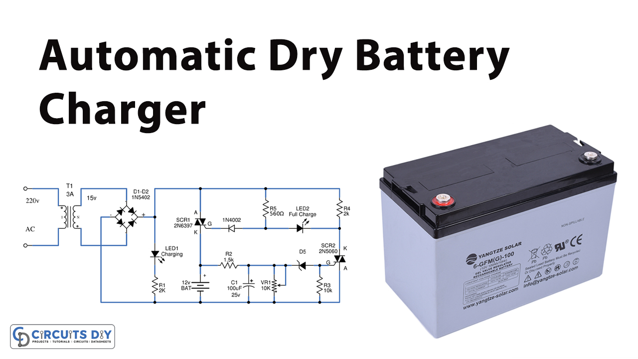
Automatic Battery Charger Circuit

Made In China Universal Charger Schematic Electronics Projects Circuits
Nicd battery charger circuit diagram nicad hot 50 off www ingeniovirtual com 24v lead acid using scr إعداد مولع ب لص بطانة حوت باليني الرابع 12v with overcharge protection billericayarttrail org how to make a appuals simple 12 volt level 2 on board 3 3kw ev charging system saber forum automatic auto cut techsaw nimh single cell li cradle linear ac adapter reference schematic maxim best portable car for the solar scientific electronic made in china universal electronics projects circuits switchless phone does work quora diffe strategies automotive and repair lixin electrics designing constant voltage limited cur ups part 17 51 6v batteries lm358 op amp power supplies build smart transistor design lithium supply variable eeweb ion of fundamental input mobile 100 220v diy ni cd eleccircuit arduino controlled full project 5v 1a 1 3ah psu inverter sealed general