Understanding the Three-Phase Dol Starter Control Circuit Diagram
Controlling electrical appliances in an efficient manner is a top priority for any property or business owner. As a result, many individuals are turning to three-phase direct-on-line (DOL) starter control circuits to provide reliable and powerful performance-based solutions that meet their particular needs. The three-phase DOL starter control circuit diagram provides a comprehensive look at how these systems operate and the essential components they contain.
In this article, we will outline the basics of three-phase DOL starters and explain the meaning of a three-Phase DOL starter control circuit diagram. Additionally, we will discuss wiring diagrams and provide some of the important safety tips on how to work with three-phase DOL starters.
What is a Three-phase Direct-on-Line (DOL) Starter?
A three-phase direct-on-line (DOL) starter is used to start, stop and protect an AC motor. It works in three-phase AC circuit and controls current at beginning and stopping of motor. This type of starter consists of three contactors that are connected in series. When connected to a three-phase source, each contactor allows the power to go through to the respective winding of the motor. The DOL starter works by sending a signal to the motor which makes it turn ON.
The DOL starter offers several benefits such as protection against overloads, low cost, and easy installation. Moreover, due to the high switching capability of the contactors, the starter can be used in both very small and very large machines.
What is a Three-Phase DOL Starter Control Circuit Diagram?
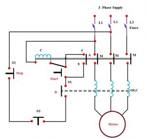
A three-phase DOL starter control circuit diagram is a schematic representation that shows the relationship among the various components that make up the starter. The diagram illustrates the main parts of the starter, how they interact with each other and the signal components of the starter that control its operation.
The diagram includes components like the main and auxiliary contacts, the overload relay, the contactor coil, and the three-phase supply. It also shows the connection between the starter and the motor and the power feeders. By analyzing the connections among the components of the starter, one can identify the faults in the system and develop an appropriate control system.
Wiring Diagrams for Three Phase DOL Starter Control System
A wiring diagram is a simplified schematic representation of an electrical circuit. Wiring diagrams show the connections between the components of the three phase DOL starter control system and are used to troubleshoot malfunctioning systems.
The wiring diagram has four basic parts: the power supply, the motor, the contactors and the overload relay. Here is a detailed breakdown of these components and their respective functions:
- Power Supply: The power supply is the source of electricity for the entire system and supplies the contactors, the overload relay, and the motor with the necessary power.
- Motor : The motor is the mechanical device that is responsible for moving and controlling the system. It is connected to the contactors and the overload relay.
- Contactors: The contactors are the main parts of the three-phase DOL starter control system that allow the necessary connections to be made between the power supply and the motor.
- Overload Relay: The overload relay provides protection against motor overloads. It is activated as soon as the current drawn from the motor exceeds the predetermined limit.
When all of these components are connected according to the wiring diagram, it is possible to control the various aspects of the system, including the starting and stopping of the motor.
Safety Tips for Working with a Three-Phase DOL Starter Control Circuit Diagram
Working with a three-phase DOL starter control circuit diagram can be dangerous if not done properly. It is important to be aware of some key safety tips before attempting to work with such a complex system.
- Turn off the power supply before working with the system. This step is imperative to ensure the safety of everyone involved.
- Use insulated tools when working with the system. This will help prevent electric shocks.
- Have a qualified electrician inspect the system regularly. This is essential to ensure that the system is functioning properly.
- Be sure to read the instructions that come with the system. This will help you understand the purpose and function of the system.
Following these tips can help to ensure that the three-phase DOL starter control circuit diagram is installed and used in a safe and efficient manner.
Conclusion
A three-phase DOL starter control circuit diagram is designed to provide an efficient and powerful performance-based solution for any property or business. It is made up of several components and a wiring diagram is necessary to understand the system. Additionally, it is important to adhere to proper safety protocols when working with the system. Following these precautionary steps can help to ensure that any installation is done in a safe and successful manner.
Mian Electric Connection Of Dol Starter To Motor Wiring For Single Phase Facebook By
How Do I Connect A Direct On Line Dol Starter To Single Phase Motor Schneider Electric Uk
How Do I Connect A Contactor And Overload To Create Direct On Line Dol Starter Schneider Electric Ireland

What Are Dol And Rdol Starters Advantages Disadvantages

Dol Starter Direct Online Wiring Diagram Working Principle Electrical4u

Dol Starter Direct Online Wiring Diagram Working Principle Electrical4u

Dol Starter Scheme And Wiring Diagram Electric Guider
Autotransformer Starter Diagram Parts Working Principle Etechnog

Direct Online Starter Construction Working Advantages Disadvantages

What Are Dol And Rdol Starters Advantages Disadvantages

3 Phase Dol Starter Motor Diagram Earth Bondhon

Dol Starter Direct Online Diagram Construction Advantages Electrical4u

Dol Starter Direct Online Diagram Construction Advantages Electrical4u

What Are Dol Starters And Their Working Principle Instrumentation Control Engineering

Direct Online Starter Dol Motor Circuit Diagram And Working Principle

Construction And Operation Of Direct Online Starter Circuit

Differences Between Dol And Star Delta Full Comparison

Starting Methods Of Induction Motor Electricalmiracles

Direct On Line Dol Motor Starter

