3 Bit Asynchronous Up Counter With Circuit Diagram And Truth Table


3 Bit Asynchronous Up Counter With Circuit Diagram And Truth Table


Asynchronous counters are an important component of digital electronics and are used in a variety of applications. A 3-bit asynchronous up counter is a basic type of digital circuit that can count from 0 to 7 in binary. This counter takes two inputs, a clock signal (CLK) and a reset signal (RST), and has three binary outputs; QA, QB, and QC. In this article, we will discuss the circuit diagram and truth table of the 3-bit asynchronous up counter and go over some of the wiring diagrams related to this particular circuit.

The 3-bit asynchronous up counter is built using flip-flops and logic gates. Flip-flops are used to store values and count up or down depending on the input signals. Logic gates are used to process the inputs and generate the appropriate output. The 3-bit counter is one of the simplest digital counters and can be used as a building block for larger and more complex circuits.

Circuit Diagram


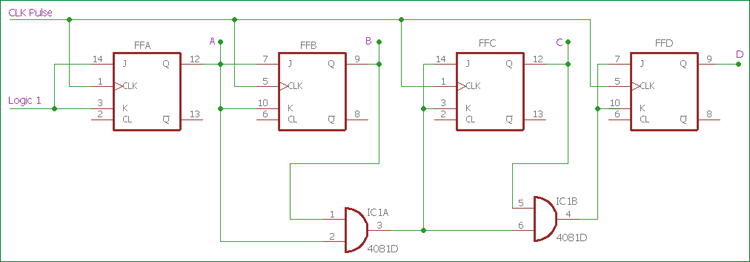
The circuit diagram of the 3-bit asynchronous up counter is shown below. It consists of three J-K flip-flops connected in series, along with the reset (RST) and clock (CLK) inputs. The outputs of each flip-flop are fed back into the clock (CLK) input of the next flip-flop.

![circuit diagram](https://i.stack.imgur.com/mjxU6.jpg)

When the CLK input is low, all the flip-flops are reset to their initial states and the outputs are set to zero. When the CLK input is high, the first flip-flop is triggered, which then triggers the second flip-flop, and so on. The output of each flip-flop is used as the input to the next flip-flop. This process continues until all three flip-flops have been triggered and the output of the last flip-flop (QC) is high.

Truth Table


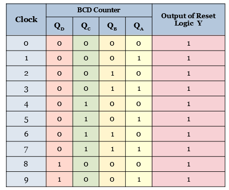
The truth table of the 3-bit asynchronous up counter is given below:

| RST | CLK | QA | QB | QC |
|:---------:|:---------:|:--------:|:--------:|:--------:|
| 0 | 0 | 0 | 0 | 0 |
| 0 | 1 | 0 | 0 | 1 |
| 0 | X | X | X | Count |
| 1 | 0 | 0 | 0 | 0 |
| 1 | 1 | 0 | 0 | 0 |

As can be seen from the truth table, the 3-bit asynchronous up counter counts up each time the clock (CLK) input goes high. When the reset (RST) input is high, the counter is reset to its initial state, with all outputs set to zero. This means that the 3-bit up counter counts from 0 to 7 in binary every time the clock input goes high.

Wiring Diagrams


The wiring diagrams for the 3-bit asynchronous up counter are relatively simple. Each flip-flop needs to be connected to the clock input and the reset input. The outputs of each flip-flop need to be connected to the clock input of the next flip-flop. The following diagram shows the wiring diagram of the 3-bit up counter.

![wiring diagram](https://i.stack.imgur.com/6X2fM.jpg)

The clock input is connected to all the flip-flops and the reset input is connected to the first flip-flop. The outputs of the first flip-flop are connected to the clock input of the second flip-flop, and so on. The outputs of the third flip-flop are the counter outputs, which can be used for various purposes.

In conclusion, the 3-bit asynchronous up counter is a simple and useful digital circuit that can be used in a variety of applications. It takes two inputs, a clock signal (CLK) and a reset signal (RST), and has three binary outputs. The circuit diagram and truth table of the 3-bit asynchronous up counter have been discussed in this article, along with the wiring diagrams related to this particular circuit.


How To Design A 3 Bit Synchronous Counter Using J K Flip Flop That Should Follow The Counting Sequence 7 1 4 5 2 0 6 And Repeat Quora

How To Design A 3 Bit Synchronous Counter Using J K Flip Flop That Should Follow The Counting Sequence 7 1 4 5 2 0 6 And Repeat Quora


Explain The Working Of A Three Bit Binary Ripple Counter Computer Engineering

Explain The Working Of A Three Bit Binary Ripple Counter Computer Engineering


Deldsim 3 Bit Up Counter

Deldsim 3 Bit Up Counter


Asynchronous And Synchronous Counters Ppt

Asynchronous And Synchronous Counters Ppt


How To Implement A 3 Bit Asynchronous Up Counter That Counts Like This 000 011 110 With T Flip Flops Quora

How To Implement A 3 Bit Asynchronous Up Counter That Counts Like This 000 011 110 With T Flip Flops Quora


Title 3 Bit Synchronous Counter Using Flip Flops Aim To Study Up Compon

Title 3 Bit Synchronous Counter Using Flip Flops Aim To Study Up Compon


Counters De Part 20

Counters De Part 20


Asynchronous Counter Definition Working Truth Table Design

Asynchronous Counter Definition Working Truth Table Design


Counters In Digital Electronics Javatpoint

Counters In Digital Electronics Javatpoint


Binary Counters

Binary Counters


Basic Digital Counter Electrical4u

Basic Digital Counter Electrical4u


Design Of Asynchronous Ripple Counter

Design Of Asynchronous Ripple Counter


Solved Experiment 9 Study Of Counters I Chegg Com

Solved Experiment 9 Study Of Counters I Chegg Com


Asynchronous Counter Definition Working Truth Table Design

Asynchronous Counter Definition Working Truth Table Design


Synchronous Counter Definition Working Truth Table Design

Synchronous Counter Definition Working Truth Table Design


Ripple Counter Circuit Diagram Timing And Applications

Ripple Counter Circuit Diagram Timing And Applications


Synchronous Counters Sequential Circuits Electronics Textbook

Synchronous Counters Sequential Circuits Electronics Textbook


Synchronous Counter Definition Working Truth Table Design

Synchronous Counter Definition Working Truth Table Design


Asynchronous Counters Sequential Circuits Electronics Textbook

Asynchronous Counters Sequential Circuits Electronics Textbook